


5
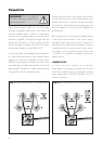
Please take note of the jumper clips installed
under the binding posts. These clips attach the
high-frequency and low-frequency sections of the
crossover together. Leaving these in place, connect
the (+) wire from your amplifier to either red (+)
binding post and the (–) wire from your amplifier to
either black (–) binding post (Fig. 1).
Only after jumper
clips are removed may you connect
individual runs of speaker cable
from your amplifiers to the high-fre-
quency and low-frequency signal input binding
posts. Damage will occur to your amplifiers if
the jumper clips are not removed.
This connection method replaces the jumper clips
installed under the binding posts with individual runs
of speaker wire from your amplifier. This doubles
the signal carrying conductors from the amplifier to
the speaker, thus direct-coupling each portion of the
crossover to the amplifier.
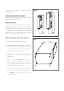
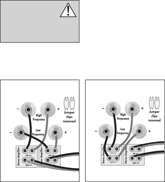
To bi-wire you must first loosen the binding posts
and remove the jumper clips. Connect one set of
wires to the upper set of binding posts which con-
nect to the high-frequency drivers. Then connect
a second set of wires to the lower binding posts
which connect to the low-frequency drivers. Next,
connect both sets of wires to the appropriate termi-
nals on your amplifier. Please take care to connect
both (+) wires to the (+) amplifier terminals and both
(–) wires to the (–) amplifier terminals. This is known
as a parallel connection (Fig. 2).
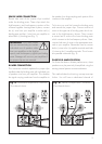
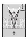
For those that desire ultimate performance, these
speakers may be passively bi-amplified using the
existing internal passive crossover elements.
This method takes the bi-wiring concept one step
further. You will have a dedicated channel of
Horizontal bi-amplification connection.
One channel shown.
Vertical bi-amplification connection.
One channel shown.