


ENGLISH
4
6. Crunch Channel Volume
This control adjusts the level of sound coming out
of the overdrive preamp channel and allows you to
balance it against the Clean channel.
7. Lead Channel Gain (OD2 - Red LED)
As 5 above but controlling the Lead channel gain,
and making even more saturated tones available.
8. Lead Channel Volume
As 6 above, this control balances the output of the
Lead channel.
✪ User Hint - When using the less gain/more level
way of driving the power stage, keep the overdrive
gain low and use this volume control to drive the
power amp.
9. Overdrive Treble, Middle, Bass
As opposed to the ‘Clean’ channel, these controls
are placed after the distortion generating circuitry
of your amp and as such affect the texture of the
tone, rather than the gain of the channel, especially
when using high levels of preamp gain.
✪ User Hint - Although many textures are available
from this relatively simple configuration, a good
starting point (again) is to set everything midway.
For a more modern ‘heavy’ tone, turn the mid
control down and boost the treble and bass. For a
more classic ‘rock’ tone bring back the mids and
bring the treble and bass down a bit.
✪ User Hint - When using the less gain / more
volume approach, the tone controls can be used to
help ‘push’ the power amp for a more refined tone.
10. Overdrive Tone Shift
Pushing in this switch reconfigures the
components used in the tone forming circuit. By
doing this the Mid frequency is shifted and
deepened, which, depending on how you set up
the tone controls will help you get a modern
‘scooped’ rock sound, i.e. cutting the Mid control.
Even though this may not be your ‘thing’, the range
of tones available can be very expressive in other
ways. As always, experiment.
11. Master FX Mix
This controls the balance of the return from the
parallel FX loop (see rear panel details for
connection) with the amps direct signal.
✪ User Hint - As the FX loop is of the parallel kind,
this is where you should use time delay effects (i.e.
echo, reverb, pitch shifting, chorus, etc.). For
optimum use the direct signal in your processor
should be turned to zero so that only the effect
signal is returned to the amp, this way the tone
integrity of the direct amp signal is unimpaired.
12. Clean Reverb
This controls the level of the internal spring reverb
circuitry from a slight shimmer to a cavernous
depth for the Clean channel only.
13. Overdrive Reverb
Controls the reverb depth for both the Crunch and
Lead channels.
Remember that the Reverb has an on/off function
on the foot controller.
14. Master Presence Control
This works on the power amp circuit, and enables
you to brighten up the sound, especially useful
when the room acoustics of where you are playing
are very dead sounding.
15. Deep Switch
Pushing in this switch activates a unique Marshall
circuit that expands the resonance of the speaker
system used, and thus gives a very deep and
resonant depth to the bass of your sound.
16. Master Volume
This controls the overall volume level of the total
amplifier, thus allowing you to set up the tone and
balance of all three channels, and then setting the
required suitable level for your requirements with
just one control. Additionally, using this control
allows you to turn up the gain of the clean channel
for a warmer, crunchier sound, without having to
have the full power of the amp blasting away.
✪ User Hint - As the (rear panel mounted) speaker
emulated D.I. output is derived from this circuit
you can balance the sound coming out of the
loudspeaker from zero to full, whilst maintaining a
constant level out of the D.I. output - ideal for
silent recording, direct to the desk.
17. Standby Switch
This turns the high voltage feed to operate the
valves on and off.
✪ User Hint - This switch should be used for (a)
allowing the amp to warm up before turning the
Standby on (at least a minute - preferably 2/3
minutes if possible) and (b) turn the Standby
switch off when taking a break (rather than turning
off the whole amp), thereby keeping your amp at
the ‘ready’, without waiting for it to warm up again.
Remember to do these two simple rules and your
valves will love you for it and should last an awful
lot longer before replacement is needed.
ENGLISH
5
18. Power Switch
This turns the mains electricity that feeds your
amp on and off. As stated before, turn this switch
on for at least a minute or two before turning the
Standby on, to allow your amp to warm up.
✪ User Hint - For environmental reasons at least,
if leaving your amp for more than a normal gig
type break or so, turn your amp off at this switch,
it will save electricity. Also, if leaving your amp
unused for a long time, always remember to
disconnect your amp’s power cord from the mains
supply, at the very least it will prevent someone
else accidentily turning it on without realising.
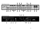
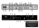
1. Footcontroller DIN Socket
This socket is used to connect the 5-way foot
controller to the amplifiers control circuit.
The footcontroller allows you to immediately
switch between all three channels, turn the reverb
on or off, and also the FX loop on or off.
2. Loudspeaker Output Select
This switch selects the output impedance of the
amplifier for either 8 or 16 ohm use, to match to
alternate speaker systems. Although more on this
will be covered later, it is important to remember
that the internal loudspeaker(s) on the TSL601 and
TSL602 combos is 16 ohms and that the amp
must be set to match that (16 ohms). Of course
the TSL60 head does not have any in built
loudspeakers, but the impedance matching rule
still applies
3. Loudspeaker Output Jacks
These are identified by having RED jack socket
nuts, and connect the amplifier output to either the
internal, or, external loudspeaker system.
WARNING! At no time must the amplifier be
allowed to run with no loudspeaker (or appropriate
loudspeaker type load) connected to its output.
Otherwise serious and expensive damage may
occur.
4. FX Loop Send Jack
Connects the TSL amp to the input of the external
FX processor.
5. Loop Level Switch.
This switch alters the signal level present in the FX
loop, allowing the connection and use of differing
makes and standards of FX units. The nominal
levels available are +4dBm (switch out) or -10dBv
(switch in).
6. FX Loop Return Jack
Connects the output of the external FX processor
back into the TSL amp circuit.
7. Speaker Emulated D.I. Out XLR.
Line level, balanced, emulated output signal for
connection into PA or recording Mixing Desks etc.
8. H.T. Fuse - See specifications for
correct value
This fuse protects your amp in the case of a fault
occurring with any of the high voltage circuitry.
The usual reason for this to blow is when an
output valve has become faulty.
9. Mains Input
Use the supplied power cord to connect your amp
to the mains supply.
10. Mains Fuse - See specifications for
correct value
This fuse provides overall safety protection in the
case of your amplifier developing a major electrical
fault.
✪ User Hint - The fuses fitted to your amp are
there to provide you with safety protection in the
case of a fault developing. If they blow it means
something is wrong, usually a valve is getting old,
but under no circumstances fit a fuse of a different
value to stop it from blowing, as this could be very
expensive in terms of safety and cost. Remember,
if a fuse blows, it has blown for a reason.
LOUDSPEAKER SYSTEMS
The TSL601 and TSL602 combo amps are each
fitted with exclusive Marshall 12” ‘Wolverine’
loudspeakers. The 601 having one 16ohm
loudspeaker, and the 602 having two 8ohm units
wired in series for 16ohm use.
TSL60, TSL601 & TSL602 Rear Panel Features (pages 32 - 35)