


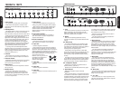
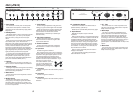
1. Power Switch
On / Off Switch for mains power to the amplifier.
Please ensure the amplifier is switched off and
unplugged from the mains electricity supply before
being moved.
2. Standby Switch
The Standby Switch is used in conjunction with the
Power Switch (item 1) to ‘warm up’ the amplifier
before use and to prolong the life of the output valves.
When powering up the amplifier always engage the
Power Switch (item 1) first. This allows the
application of the voltage required to heat the valves
to their correct operating temperature. After about 2
minutes, when the valves are up to the correct
temperature, the Standby Switch can be engaged.
Upon doing this the H.T. (High Tension) which is the
high voltage required by the output valves to pass
signal (and hence produce sound) is applied.
To prolong valve life, the Standby Switch alone
should be used to turn the amplifier on and off during
breaks in a performance. Also, upon full power down,
always disengage the Standby Switch prior to the
main Power Switch (item 1).
3. Indicator
The Indicator will be lit when your amplifier is on
and will not be lit when the amplifier is switched off.
4. Speed Control
Controls the speed of oscillation when using the
tremelo effect.
5. Intensity Control
Controls the intensity of oscillation (i.e. the effect
depth) when using the tremelo effect.
Note: The tremelo effect will only work when playing
through Channel 2 of the Bluesbreaker combo.
6. Presence Control
Adds higher frequencies to the guitar tone, creating
crispness and bite. Turning this up will make the
sound more cutting and ‘present’.
7. Bass Control
Controls the amount of low frequencies or bottom
end in your tone.
8. Middle Control
Dictates the middle register of the amplifier.
Turning this up will make your guitar sound fatter.
Conversely reducing the amount of middle in your
tone will result in a sharper and thinner guitar sound
for a more ‘scooped’ tone.
9. Treble Control
Controls the high frequencies of the guitar tone,
making your guitar sound brighter when increased.
(Note: The tone network is highly interactive and
altering one control can change the shape of the
sound in relation to the other tone controls.
Experimentation is the best way to achieve your
desired sounds.)
10. Volume I
Controls the overall output level of Channel 1.
Note: This channel is voiced for a higher treble
response than Channel 2.
11. Volume II
Controls the overall output level of Channel 2.
Note: Channel 2 is voiced for normal response.
12. Input Jack
Connects the guitar to Channel 1.
Note: Though the first input of the first channel is
the input that most guitarists use, don’t be afraid to
experiment. Some guitar players prefer to mix the
two channels together by connecting a short,
screened patch lead between the second input of
Channel 1 and the first input of Channel 2. If you then
plug your guitar into the first
input of Channel 1 (item 12), you
can mix the different tonal
characters of each channel for
greater flexibility. (See diagram).
13. Input Jack
Connects the guitar to the lower sensitivity input on
Channel 1.
14. Input Jack
Connects the guitar to Channel 2.
15. Input Jack
Connects the guitar to the lower sensitivity input on
Channel 2.
87
SPEED INTENSITY PRESENCE BASS MIDDLE TREBLEMAINS
ON ON
STANDBY
INPUTS
1
1
2
2
0
28
6
4
10 0
28
6
4
10 0
28
6
4
10 0
28
6
4
10 0
28
6
4
10 0
28
6
4
10
VOLUME I VOLUME II
0
28
6
4
10 0
28
6
4
10
JTM
1962 Front Panel
1 2 3 4 5 6 7 8 9 10 11 13
12 14
15
MANUFACTURED BY
MARSHALL AMPLIFICATION PLC
BLETCHLEY, MILTON KEYNES, ENGLAND.
OUTPUT
SELECTOR
FOOTPEDAL
MAINS INPUT MAINS FUSE
T1.6A 230V
T3.15A 117V
H.T. FUSE
T500 mA
CONNECT SPEAKERS BEFORE USE
OUTPUT: 30 WATTS RMS
WARNING!: RISK OF HAZARDOUS ENERGY
AVIS!: ENERGIE ELECTRIQUE DANGEREUSE!
!
SPEAKERS
117V ~ 60Hz
175 W
atts
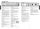
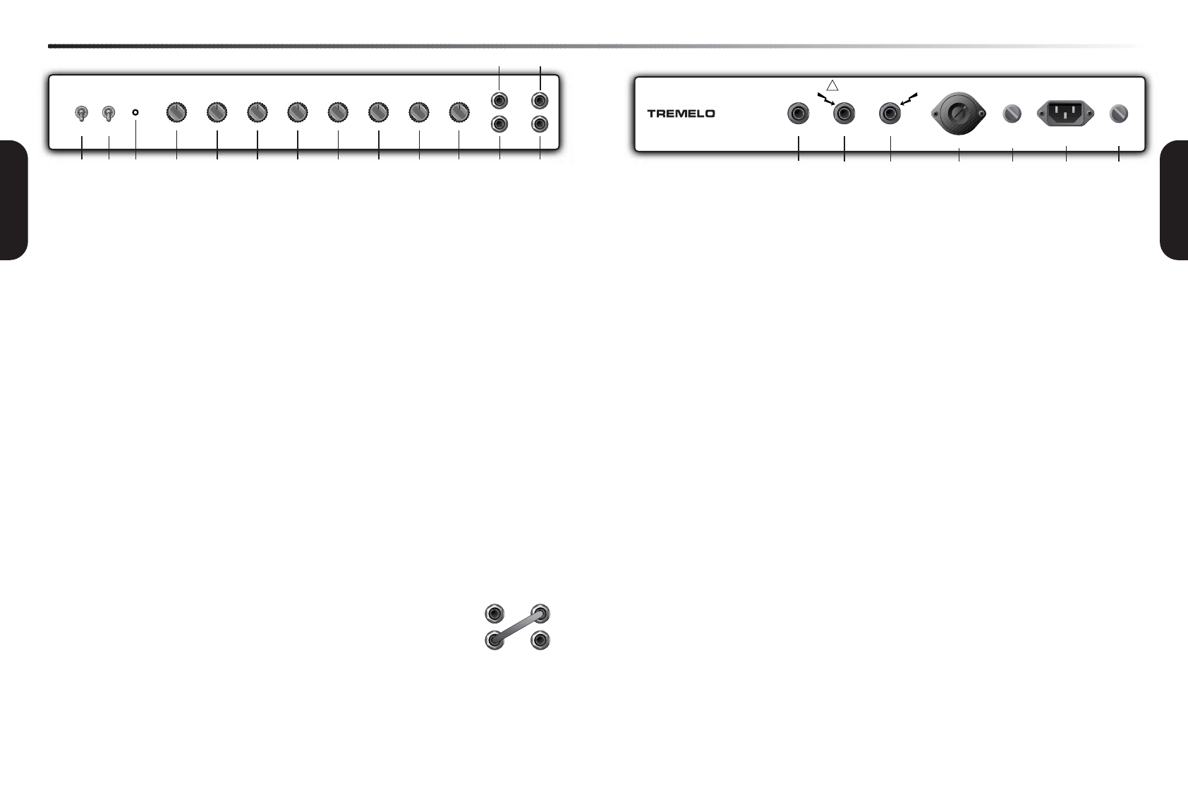
1. Footpedal Jack
For connection of the supplied footswitch to allow
tremelo to be switched on and off.
Note: The tremelo effect will only work when playing
through Channel 2.
2/3. Loudspeaker Outputs
These are for connection to either the internal
speakers and/or an external load, i.e. speaker
extension cabinet(s). (See item 4).
4. Output Selector
Matches the amplifier’s output to the load
impedance.
With all-valve amplifiers it is imperative that the
amplifier is connected to a load whilst in operation
and that the impedance selected on the amplifier
matches the total impedance of the internal speakers
and/or extension speaker cabinets.
The two internal speakers are 16 Ohms each. These
are wired in parallel giving an overall impedance of
8 Ohms, therefore the output selector should be set to
8 Ohms.
If an additional 8 Ohm extension speaker cabinet is
used in conjunction with the internal speakers the
output selector should be set to 4 Ohms.
Note: No additional extension speaker cabinet with
an impedance lower than 8 Ohms should be used in
conjunction with the internal speakers.
Failure to comply with these points will result in
damage to the amplifier.
Your amp should be completely powered down
before the selector is turned.
5. H.T. Fuse
The correct value of H.T. fuse is specified on the
rear panel of the amplifier. Please refer to Important
Safety Instructions, page 2.
6. Mains Input
Your amp is provided with a detachable mains
(power) lead which is connected here. The specific
mains input voltage rating that your amplifier has
been built for is shown on the back panel. Before
connecting for the first time, please ensure that your
amplifier is compatible with your electricity supply. If
you have any doubt, please get advice from a
qualified person. Your Marshall dealer will help in this
respect.
7. Mains Fuse
The correct value of mains fuse is specified on the
rear panel of the amplifier. Please refer to Important
Safety Instructions, page 2.
1962 Rear Panel
1 2 3 4 5 6 7
ENGLISH
ENGLISH
INPUTS
1
1
2
2
1962 (Bluesbreaker)