27
Biamplification
In contrast to bridged operation (wherein a two channel amplifier is “fooled” into
behaving as a single, larger amplifier), biamplification makes use of a two-channel
amplifier to drive different portions of a single loudspeaker. As with bridging, it
offers a modular way of increasing the overall performance of your system (if
your loudspeakers support biamplification).
Since each channel of the amplifier is delivering current into its load only over a
limited range of frequencies (typically bass vs. mids and treble), several forms of
distortion are reduced as compared to each channel handling the full range of
musical information. For this reason, many loudspeaker companies are designing
their products to include multiple speaker inputs (since using multiple amplifiers
improves the performance of their products as well). Another common use of
biamplification involves adding a subwoofer (along with an appropriate electronic
crossover) to supplement and/or improve the deep bass performance of your
system.
Always refer to the specific directions provided by your loudspeaker manufacturer
prior to setting up a biamplified speaker system. Any instructions contained
herein cannot be substituted for those that are specific to the loudspeaker in
question. In general, however, biamping is done in one of two ways: active
biamplification, or passive biamplification.
Active biamping refers to the presence of an “active” electronic crossover that di-
vides the music into two (or sometimes more) bands of frequencies. These are
then forwarded to separate power amplifiers, and sent on directly to the appro-
priate drivers in the speakers. The most common application of this approach is
the use of a subwoofer crossover to separate the deep bass (below, say, 80 Hz)
from the rest of the program material. It is then amplified separately and sent to a
dedicated subwoofer designed to handle those extremely low frequencies.
Apart from adding a subwoofer, the next most common form of biamping (called
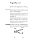
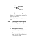
passive biamplification) involves merely using a conventional “Y-adapter” (either
balanced or single-ended) to provide a full range signal to two channels.
Balanced Y-adapter
21
3
12
3
12
3
Female XLR Input
Pin 1: signal ground
Pin 2: signal + (non-inverting)
Pin 3: signal – (inverting)
Male XLR Output
Pin 1: signal ground
Pin 2: signal + (non-inverting)
Pin 3: signal – (inverting)
Male XLR Output
Pin 1: signal ground
Pin 2: signal + (non-inverting)
Pin 3: signal – (inverting)
The outputs of these two channels are then connected to two sets of binding
posts on each loudspeaker. (See below.) The loudspeaker’s internal crossover con-
tinues to divide the frequencies appropriately among the various drivers.


