


15 16
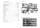
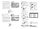
7. DC OFFSET VOLTAGE ALIGNMENT
1. Before switching the mains switch. Turn down the
master volume to the minimum position and set the
balance volume and tone volumes at the center po-
sitions. Set variable resistors R627(on the PCB
P601:L ch) and R727(on the PCB P701:R ch) fully
counterclockwise.
2. Connect the digital voltage meter to the speaker
terminal. And set the digital voltage meter for the
DC position.
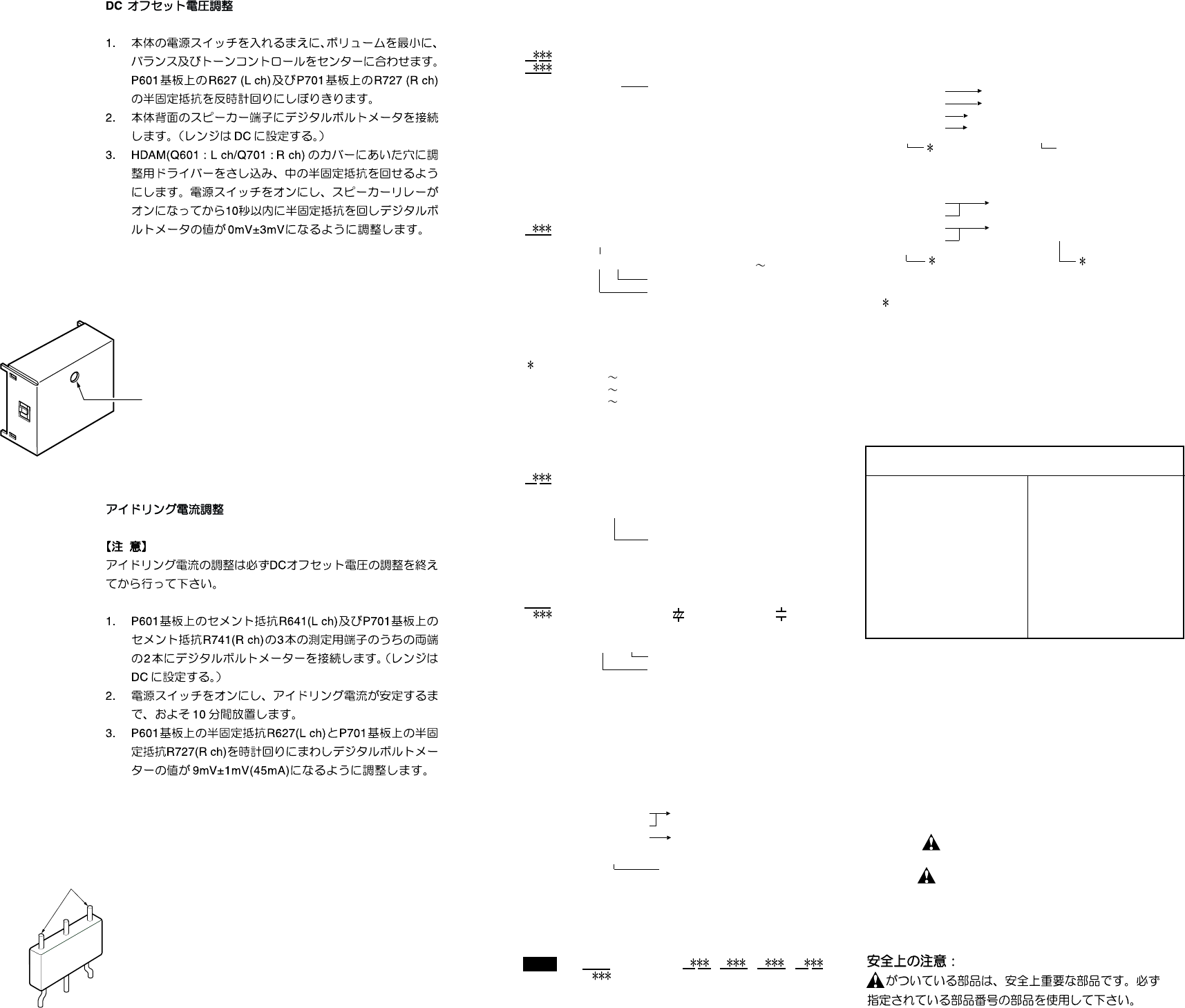
3. Turn the mains switch ON. Put thin adjustment screw
driver in to the hole of the HDAM (Q601:L ch /
Q701:R ch) copper cover. Adjust variable resis-
tors in the HDAM (Q601:L ch / Q701:R ch) value at
0mV±3mV with in 10 seconds after speaker relay
turn ON.
8. IDLING CURRENT ALIGNMENT
REMARK
Before “Idling current alignment”, “ DC offset voltage
alignment “ have to be done!!
1. Each of cement resistor R641(on the PCB P601:Lch) and
cement resistor R741(on the PCB P701:Rch) are provided
with three test points. Connect the digital voltage meter,
set for the DC voltage input, to the test points at the two
extremities of three test points of R641(L ch) and R741(R
ch).
2. After the setup above, turn the mains switch ON and
heat up the amplifier about 10 minuetes.
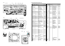
3. Adjust variable resistors R627(on the PCB P601:L
ch) and R727(on the PCB P701:R ch) according to
the digital volt meter reading. The target setting
value is 9mV±1mV(45mA) for both L ch and R ch.
Alignment
hole
Measurement point
R641 / R741
SM970926ACT
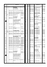
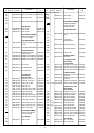
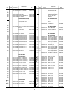
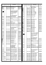
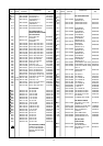
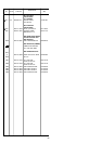
9. ELECTRICAL PARTS LIST
The suppliers and their type numbers of fusible resistors
are as follows;
1. KOA Corporation
Part No. (MJI) Type No. (KOA) Description
NH05 × × × 140 RF25S × × × × ΩJ(±5% 1/4W)
NH05 × × × 120 RF50S × × × × ΩJ(±5% 1/2W)
NH85 × × × 110 RF73B2A × × × × ΩJ(±5% 1/10W)
NH95 × × × 140 RF73B2E × × × × ΩJ(±5% 1/4W)
2. Matsushita Electronic Components Co., Ltd
Part No. (MJI) Type No. (MEC) Description
NF05 × × × 140 ERD-2FCJ × × × (±5% 1/4W)
RF05 × × × 140
NF02 × × × 140
ERD-2FCG
× × × (±2% 1/4W)
RF02 × × × 140
Examples ;
Resistance value
0.1 Ω.... 001 10 Ω .... 100 1 kΩ .... 102 100 kΩ .... 104
0.5 Ω.... 005 18 Ω .... 180 2.7 kΩ ....272 680 kΩ.... 684
1 Ω.... 010 100 Ω .... 101 10 kΩ .... 103 1 MΩ.... 105
6.8 Ω.... 068 390 Ω .... 391 22 kΩ .... 223 4.7 MΩ.... 475
ASSIGNMENT OF COMMON PARTS CODES.
RESISTORS
R : 1) GD05 × × × 140, Carbon film fixed resistor, ±5% 1/4W
R : 2) GD05 × × × 160, Carbon film fixed resistor, ±5% 1/6W
Examples ;
Resistance value
0.1 Ω.... 001 10 Ω .... 100 1 kΩ .... 102 100 kΩ.... 104
0.5 Ω.... 005 18 Ω .... 180 2.7 kΩ ....272 680 kΩ.... 684
1 Ω.... 010 100 Ω .... 101 10 kΩ .... 103 1 MΩ.... 105
6.8 Ω.... 068 390 Ω .... 391 22 kΩ .... 223 4.7 MΩ.... 475
Note : Please distinguish 1/4W from 1/6W by the shape of parts
used actually.
CAPACITORS
C : CERAMIC CAP.
3) DD1 × × × × 370, Ceramic capacitor
Disc type
Temp.coeff.P350 N1000, 50V
Examples ;
Tolerance (Capacity deviation)
±0.25 pF .... 0
±0.5 pF .... 1
±5% .... 5
Tolerance of COMMON PARTS handled here are as follows :
0.5 pF 5 pF .... ±0.25 pF
6 pF 10 pF .... ±0.5 pF
12 pF 560 pF.... ±5%
Capacity value
0.5 pF .... 005 3 pF ....030 100 pF .... 101
1 pF ....010 10 pF .... 100 220 pF .... 221
1.5 pF .... 015 47 pF ....470 560 pF .... 561
C : CERAMIC CAP.
4) DK16 × × × 300, High dielectric constant ceramic
capacitor
Disc type
Temp.chara. 2B4, 50V
Examples ;
Capacity value
100 pF ....101 1000 pF ....102 10000 pF .... 103
470 pF ....471 2200 pF ....222
C : 5) ELECTROLY CAP. ( ), 6) FILM CAP. ( )
5) EA
× × × × × × 10, Electrolytic capacitor
One-way lead type, Tolerance ±20%
Examples ;
Capacity value
0.1 µF....104 4.7 µF ....475 100 µF ....107
0.33 µF....334 10 µF ....106 330 µF ....337
1 µF....105 22 µF ....226 1100 µF ....118
2200 µF ....228
Working voltage
6.3V....006 25V ....025
10V....010 35V ....035
16V....016 50V ....050
6) DF15 × × × 350 Plastic film capacitor
DF15 × × × 310 One-way type, Mylar ±5% 50V
DF16 × × × 310 Plastic film capacitor
One-way type, Mylar ±10% 50V
Examples ;
Capacity value
0.001 µF(1000 pF) ....... 102 0.1 µF....104
0.0018 µF........................ 182 0.56 µF....564
0.01 µF........................ 103 1 µF....105
0.015 µF........................ 153
: 1) The above CODES ( R , R , C , C and
C ) are omitted on the schematic diagram in some
case.
2) On the occasion, be confirmed the common parts on
the parts list.
3) Refer to “Common Parts List” for the other common
parts (RI05, DD4, DK4).
➀
➁
Capacity value
Tolerance
➃
Capacity value
Resistance value
➄
Working voltage
Capacity value
➆
Capacity value
NOTE
NOTE ON SAFETY FOR FUSIBLE RESISTOR :
Resistance value
Resistance value
(0.1 Ω − 10 kΩ)
Resistance value
Resistance value
ANT. : ANTENNA BATT. : BATTERY
CAP. : CAPACITOR CER. : CERAMIC
CONN. : CONNECTING DIG. : DIGITAL
HP : HEADPHONE MIC. : MICROPHONE
µ-PRO : MICROPROCESSOR REC. : RECORDING
RES. : RESISTOR SPK : SPEAKER
SW : SWITCH TRANSF. : TRANSFORMER
TRIM. : TRIMMING TRS. : TRAMSISTOR
VAR. : VARIABLE X’TAL : CRYSTAL
ABBREVIATION AND MARKS
{
{
{
{
{
{
{
{
{
{
➂
➀
➁
➂
➃
➄
➅
➆
➅
NOTE ON SAFETY :
Symbol Fire or electrical shock hazard. Only original
parts should be used to replaced any part marked with
symbol
. Any other component substitution (other
than original type), may increase risk of fire or electrical
shock hazard.