7
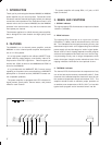
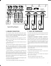
4. SPEAKER CONNECTIONS
This equipment, being a high audio output power ampli-
fier, has a hazardous energy at its speaker terminal. Please
be sure to make an appropriate speaker connection ac-
cording to the following procedure:
- Confirm that the power switch of the equipment is at "OFF"
position. If it is at "ON", turn it to "OFF" position to con-
nect a speaker cable.
- Use a speaker cable with the flame retardant rating of
type SPT12 or more.
- For bare wire connections, strip the insulation off no more
than 3/8" at the speaker terminal connection of speaker
cable, and twist the exposed wire. For banana-type plugs
or spade terminals, follow the instructions of the connec-
tor manufacturer.
- Connect speakers in correct polarity, according to the
indication for the polarity of speaker terminals. For bare
wire or spade terminal connections, first loosen the speaker
terminal by turning in a counter-clockwise direction, insert
the bare wire or spade terminal, then re-tighten by turning
the terminal clockwise.
- Prevent any stress from being applied to the speaker cable
connected to the speaker terminal.
- Don't touch the speaker terminals during operation.
6. CARE AND MAINTENANCE
This section describes the car and maintenance tasks that
must be performed to optimize the operation of your
marantz equipment.
CLEANING OF EQUIPMENT EXTERNAL SURFACES
The exterior finish of your unit will last indefinitely with
proper care and cleaning. Never use scouring pads, steel
wool, scouring powders or harsh chemical agents (e.g. lye
solution), alcohol, thinners, benzine insecticide or other
volatile substances as these will mar the finish of the equip-
ment.
Likewise, never use cloths containing chemical substances.
If the equipment gets dirty, wipe the external surface with
a soft, lint free cloth.
If the equipment becomes heavily soiled:
- Dilute some washing up liquid in water, in a ratio of one
part detergent to six parts water.
- Dip a soft, lint free cloth in the solution and wring the
cloth out until it is damp.
- Wipe the equipment with the damp cloth.
- Dry the equipment by wiping it with a dry cloth.
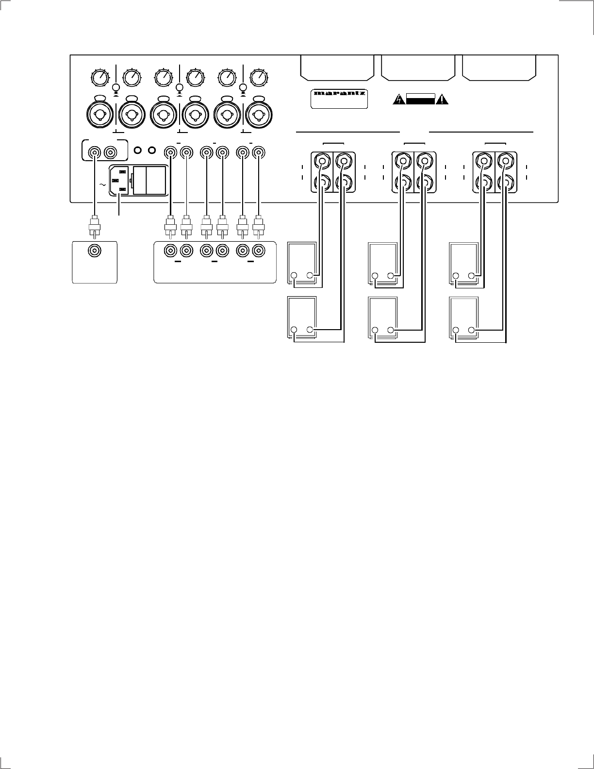
Typical Wiring Diagram
CH1
(1-2 MONO)
STEREO
BRIDGE MONO
CH 2
CH 2CH 1
( MONO)
0
1
2
3
4
5
6
7
8
9
10
0
1
2
3
4
5
6
7
8
9
10
CH3
(1-2 MONO)
STEREO
BRIDGE MONO
CH 4
CH 4CH 3
( MONO)
0
1
2
3
4
5
6
7
8
9
10
0
1
2
3
4
5
6
7
8
9
10
CH5
(1-2 MONO)
STEREO
BRIDGE MONO
CH 6
CH 6CH 5
( MONO)
0
1
2
3
4
5
6
7
8
9
10
0
1
2
3
4
5
6
7
8
9
10
RC-5 REMOTE
CONTROL
IN OU T
DC TRIGGER
OUTIN
CH1 CH2 CH3 CH4 CH5 CH6
AC
REPLACE ONLY WITH
SAME TYPE FUSE
REFER TO OWNER'S MANUAL
FOR PROPER FUSE RATING
STEREO MODE
150W / CHAN - 8 OHMS
250W / CHAN - 4 OHMS
MODEL NO. MM9360
115V
50/60Hz 1400W
BRIDGE MODE
500W BRIDGE - 8 OHMS
BRIDGE
+
-
(+)
CH 1
(-)
(+)
CH 2
(-)
OUTPUTS
BRIDGE
+
-
(+)
CH 3
(-)
(+)
CH 4
(-)
BRIDGE
+
-
(+)
CH 5
(-)
(+)
CH 6
(-)
BRIDGE MODE
TAKE OUTPUT FROM
TWO RED POSTS
DO NOT CONNECT EITHER
OUTPUT WIRE TO GROUND
MANUFACTURED IN THE USA BY ASHLY AUDIO INCORPORATED
CAUTION
RISK OF ELECTRIC SHOCK
DO NOT OPEN
PUSH
PUSH
PUSH PUSH PUSH PUSH
- +
- +
Typical Surround Preamplifier Outputs
LR LR CenSub
Front Surround Center
- +
- +
- +
- +
Front
-L-
-R-
Surround
-L-
-R-
Center
Center
Sub
Marantz
Remote
Control
Out
To
Power
Outlet


