


OPERATIONAL NOTES
BEFORE POWER-UP
Once placed, join the power supply cable to the pre-amplifier via the large16-pin circular
connector. The 16-pin connectors are keyed and can only be mated when both halves are lined up
correctly. Check and make sure the power supply is switched off, then attach the grounded IEC
power cable jack to the IEC plug. Keep the power off until all other system connections are
completed.
Proceed by connecting the input and output cabling to the signal sources and loads as
desired. Tie any separate turntable or tonearm ground lead to the gold CHASSIS ground binding
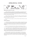
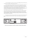
Set the GAIN dB control to 55 dB and VOLUME control to about 9 o’clock. Choose the
MM or an MC input, as necessary, with the INPUT control. Place the LOAD Z switch to a value
at or near that recommended by the cartridge manufacturer. Adjust the LOAD CAP switches to a
value at or near that recommended by the cartridge manufacturer less any interconnect cable
capacitance. Select and clean, if necessary, your favorite gramophone record....
Plug the power cable in and place the power supply’s mains power switch in the on (|)
position. The STANDBY switch should glow. Push the STANDBY switch. The STANDBY
switch will go dark, selected INPUT and GAIN blue LED’s will illuminate, the MUTE switch
lamp will start flashing and the power supply pilot LED and the MANLEY STEELHEAD badge
will light up.
PREPARATION FOR INSTALLATION
Budget a suitable space in which to place the preamplifier, power supply and associated
interconnect cable. This space should be free of strong external magnetic and RF fields, and
reasonably removed from strong loudspeaker-generated acoustical fields. This space should also
be free of excessive heat or dust and large enough to permit easy flow of cool air to the top, bottom
and sides of the preamp and power supply.
Make sure the power supply’s mains voltage selector switch is set to match the local line
voltage, and the wire link is present between the preamp’s green CHASSIS and black CIRCUIT
ground mini binding posts on the rear panel.
Try to position the power supply away from any interconnect cables which may be carrying
audio signals.
Page 9
DI
DI
M
MUTE
MUTE
SUM
SUM
VOLUME
VOLUME
LINE
LINE
SLEEP
SLEEP
0
1
2
3
4
5
6
7
8
9
10
10
x10
x10
LOAD
LOAD
CAP
CAP
pF
pF
s
2
3
4
0
0
2
0
MC LOAD Z, ohm
MC LOAD Z, ohm
5
x100
x100
10
10
9
8
7
6
5
4
2
1
0
0
5
0
100
100
10
10
9
8
7
6
5
4
3
2
1
0
MANLEY
MANLEY
STEELHEAD
STEELHEAD
0
LOAD
LOAD
CAP
CAP
pF
pF
1
2
3
4
5
6
7
8
9
10
10
x100
x100
x10
x10
1
2
MC
MC
MM
MM
50
50
55
55
60
60
65
65
GAIN dB
GAIN dB
MC
MC
INPUT
INPUT