


MANLEY LABORATORIES
13880 MAGNOLIA AVE., CHINO, CA 91710
PHONE (909) 627-4256 FAX (909) 628-2482
email: emanley@manleylabs.com
UNBALANCED
ONLY OUTPUT
AN EVEANNA MANLEY PRODUCTION
DESIGNED BY HUTCH
BALANCED or
UNBAL INPUT
+4dBu /-10 dBv
BALANCED or
UNBAL INPUT
+4dBu / -10 dBv
SERIAL NUMBER
POWER
BALANCED OUTPUT
BALANCED INPUT
CHANNEL 1
CHANNEL 2
BALANCED OUTPUT
BALANCED INPUT
TO REDUCE THE RISK OF ELECTRIC
SHOCK DO NOT EXPOSE THIS
EQUIPMENT TO RAIN OR MOISTURE
CAUTION - RISK OF ELECTRIC
SHOCK. DO NOT OPEN.
REFER SERVICING TO QUALIFIED
PERSONNEL ONLY
REPLACE FUSE
WITH SAME
TYPE AND
RATING
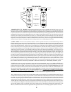
BALANCED OR UNBALANCED INPUT
SLEEVE = SHIELD = GROUND
TIP = HOT = SIGNAL POSITIVE
RING = LOW OR GROUND
IMPEDANCE = 20K OHM NOMINAL
CIRCUIT
CHASSIS
GROUND
TRANSFORMER BALANCEDOUTS
PIN 1 = SHIELD = GROUND
PIN 2 = HOT = POSITIVE PHASE
PIN 3 = LOW = NEGATIVE PHASE
WHEN RACK MOUNTING:
LEAVE SPACE FOR
VENTILATION AND FOR
MAGNETIC FIELDS FROM
OTHER EQUIPMENT TO
AVOID HUM PICK-UP !
REFER TO OWNERS MANUAL
FOR SWITCHING THIS UNIT
FOR -10dBv SIGNAL LEVELS
UNBALANCED
ONLY OUTPUT
UNBALANCED 1/4" OUTPUTS
+4 dBu / -10dBv
+4dBu / -10dBv
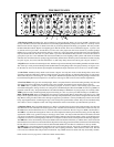
1 2 3 4
5
6
7
8
9
10
11
12
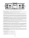
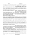
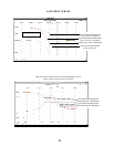
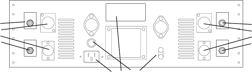
First connect all the cables, then turn on the power, wait 30 seconds, then have fun, as if we had to tell you....
1) POWER CONNECTOR. First verify the POWER SWITCH on the front panel is off (CCW). Use the power cable supplied with your
Massive Passive. One end goes here and the other end goes to the wall outlet. You know all this.
2) VOLTAGE LABEL (ON SERIAL STICKER). Just check that it indicates the same voltage as is normal in your country. It should
be. If it says 120V and your country is 220V, then call your dealer up. If it says 120V and you expect 110 it should work fine.
3) FUSE. Unplug the power cable first. The Fuse Cap needs a push then turn a quarter twist CCW to pull off. Fuses are meant to "blow"
when an electrical problem occurs and is essentially a safety device to prevent fires, shocks and big repair bills. Only replace it if it has
"blown" and only with the same value and type (2A slow-blow for 120V, 1A slow-blow for 220V). A blown fuse either looks blackened
internally or the little wire inside looks broken. A blown fuse will prevent all the LEDS from lighting and will prevent any power and audio.
4) GROUND TERMINALS. You probably don't need to worry about these. Normally there is a metal strip joining CIRCUIT and
CHASSIS Grounds. This is the first place to look if you get a hum. Make sure the strap hasn't fallen off or use a piece of wire to join the
terminals. The CIRCUIT Ground is the internal audio ground (including the 1/4" jack sleeves). The CHASSIS Ground is the metal chassis,
third pin electrical ground and pin 1 of the XLRs. Some studios use special grounding practices and these terminals are meant to make it
easy to hook up this unit for a wide variety of installations. They also help with troubleshooting hum problems.
5) PHONE JACK INPUT. (Channel One or Left) Accepts balanced or unbalanced sources. Factory set-up for +4dBu pro levels. There
are some DIP switches internally that can change this to -10dBv semi-pro or hi-fi levels. The pin out is as follows: Tip = Positive = Hot,
Ring = Negative = Low or ground, Sleeve = Circuit Ground. If you use TRS plugs be sure that the ring is connected to the negative or ground
and not "open". Input impedance is 20K ohms. See page 16 & 17 for the DIP Switch details.
6) XLR JACK INPUT. (Channel One or Left) Accepts balanced or unbalanced sources. Only for +4dBu pro levels. The DIP switches
have no effect on the XLRs. The pin out is as follows: PIN 2 = Positive = Hot, PIN 3 = Negative = Low or ground, PIN 1 = Chassis Ground.
Be sure that the PIN 3 is connected to the negative or ground and not "open" or a 6dB loss or loss of signal will happen. In general, the XLRs
and +4 pro levels are slightly preferable over phone plugs especially if gold plated matching XLRs and good cable are used.
7) XLR JACK OUTPUT. (Channel One or Left) Transformer Balanced and Floating. Only for +4dBu pro levels. The DIP switches have
no effect on the XLRs. The pin out is as follows: PIN 2 = Positive = Hot, PIN 3 = Negative = Low or ground, PIN 1 = Chassis Ground.
Be sure that the PIN 3 is connected to the negative or ground and not "open" or a complete loss of signal will happen. Output impedance
is 150 ohms and output levels can reach +37 dBv (hot) which may distort the next piece in the chain.
8) PHONE JACK OUTPUT. (Channel One or Left) Unbalanced output only. Factory set-up for +4dBu pro levels. There are some DIP
switches internally that can change this to -10dBv semi-pro or hi-fi levels (with a phase reverse). The pin out is as follows: Tip = Positive
= Hot, Sleeve = Circuit Ground. If you use TRS plugs be sure that the ring is connected to the negative or ground and not "open". See page
16 & 17 for the DIP Switch details.
9) PHONE JACK INPUT. (Channel Two or Right) Same as 5 above.
10) XLR JACK INPUT. (Channel Two or Right) Same as 6 above.
11) XLR JACK OUTPUT. (Channel Two or Right) Same as 7 above.
12)PHONE JACK OUTPUT. (Channel Two or Right) Same as 8 above.
4
THE BACK PANEL