


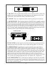
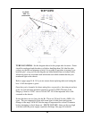
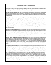
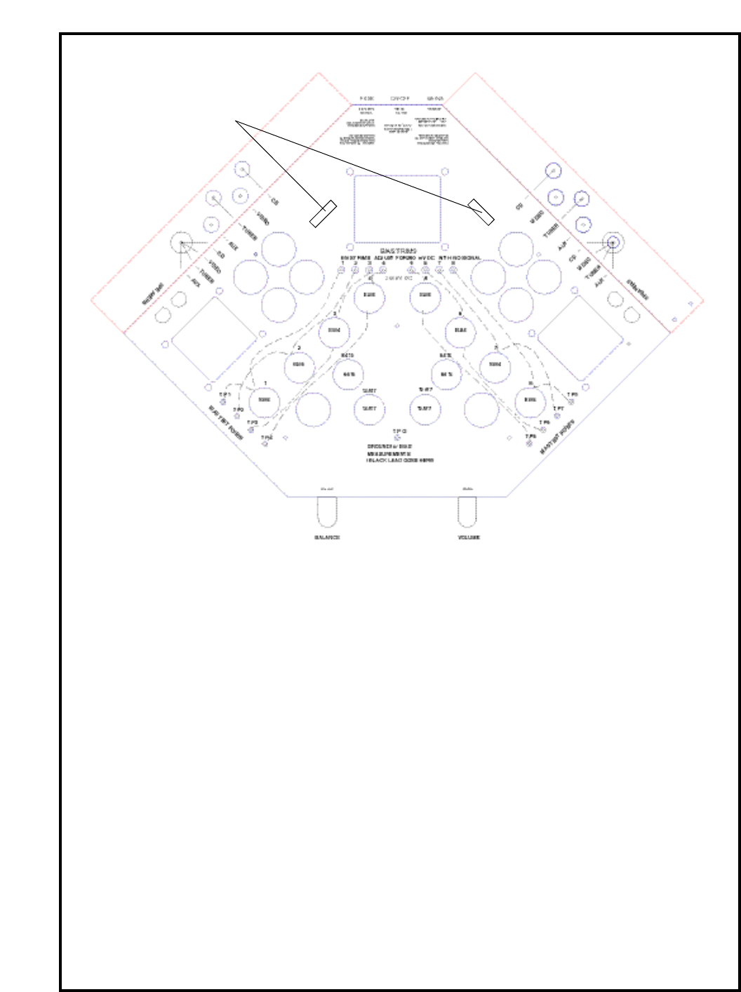
TOP VIEW
TUBE LOCATIONS - See the diagram above for the proper tube locations. Power
should be unplugged and the tubes cool before handling them. We label the tube
sockets, test points and trimmers to help. It is possible to put tubes in wrong if you
bend the pins - not good. On this diagram we added dashed lines to further clarify
which test points are associated with which tube and which trimmer but they are
numbered right on the chassis.
Refer to pages page 14 & 15 if you are unsure about replacing tubes and setting the
bias. A full description is given.
Once that you've learned a bit about setting bias, we provide a bias trim pot and test
point for each tube that should be referred to ground or TPG (The butt of the
Stingray). Aim for .25 DC volts or 250 mV DC. All of the important info is silk-
screened on the chassis.
Notice that there are two fuses for the B+. These are 250 mA Slo-blo ( MDL 1/4)
types. They are supposed to blow with some types of tube shorts and prevent
damage to the amps. ALWAYS let the amps sit unpowered for at least 20 minutes
before attempting to check them out - SHOCK HAZARD - there can be very high
volts here until the power supply capacitors discharge. See page 8 for details.
10
B+ FUSE
MDL 1/4
(underneath)