


19
To Nº38 Master To Nº33 Slave In
Locking tabLocking tab
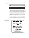
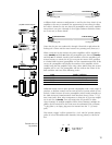
A different Link connector configuration is used for the “daisy-chain” of one
amplifier to the next, to minimize the opportunity for mis-wiring. In effect,
this cable is identical to the one between preamplifier and power amplifier
except that it uses pins 1 through 6 of an eight-conductor modular connec-
tor at one end, as shown below:
To Nº33 Slave Out To Nº33 Slave In
Locking tabLocking tab
(Note that the pins are numbered 1 through 8 from left to right when the
locking tab is down and the metal contacts are pointing away from you.)
When connected in this manner, the power amplifiers will be toggled be-
tween
standby and fully on when the preamplifier goes between standby
and fully on. In addition, should a fault condition cause the amplifier’s pro-
tection circuitry to activate, the Nº33 can report the nature of the problem
to a linked Mark Levinson preamplifier via this communications link. If this
occurs, the preamplifier will display the number of the amplifier at fault
(AMP1 being the first amplifier in the daisy chain, AMP2 being the second
amplifier, and so on). The preamplifier will also indicate the nature of the
fault condition with one of the following codes:
Code Fault Condition
HOT! thermal shutdown
DCO! uncorrectable DC offset
ZAP! excessive output current
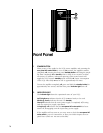
Additional remote turn-on jacks provide compatibility with a wide range of
products, to facilitate remote turn-on and turn-off in systems which do not
include a Mark Levinson 30-series preamplifier (which would normally use
the Mark Levinson Communications Link described above). These
1
⁄8" (3.5
mm) “mini-jacks” allow other components to bring the Nº33 power amplifi-
ers in and out of standby. Two such mini-jacks are provided to allow
“daisy-chaining” of multiple amplifiers. When “daisy-chaining” multiple am-
plifiers, the last mini-jack in the chain must be terminated with a dummy
1
⁄8" plug [that is, an empty plug must be inserted into the
1
⁄8" (3.5 mm)
jack].
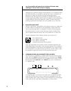
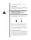
This remote “trigger” will be operated by a 3–12 volts DC positive-polarity
pulse, of at least 100 milliseconds duration, with tip polarity as shown be-
low:
Remote turn-on
tip polarity
+–
3-12 volts for at
least 100 mS
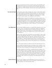
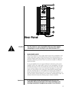
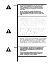
digital input
master
analog output
digital output
slave in
slave out
Link
cable
Link
cable
Nº38
slaveany input
MADRIGAL AUDIO LABORATORIES
R
polarity
invert
display
intensity
aes/ebu emphasis
123456
standby
COMPACT DISC DRIVE
Nº 37
mode
teach ir
Nº36
MADRIGAL AUDIO LABORATORIES
R
polarity
invert
display
intensity
aes/ebu emphasis
123456
standby
DIGITAL PROCESSOR
Nº 36
mode
teach ir
MADRIGAL AUDIO LABORATORIES
R
standby
PREAMPLIFIER
Nº38
MADRIGAL AUDIO LABORATORIES
R
REFERENCE
MONAURAL
AMPLIFIER
Nº 33
MADRIGAL AUDIO LABORATORIES
R
REFERENCE
MONAURAL
AMPLIFIER
Nº 33
slave out
slave in
Link
cable
Link
cable
master
slave in
(any Mark Levinson transport)
Nº33