


15
These two RJ-45 communications ports also support the PHAST™ inter-
component communications protocols, greatly simplifying the design and
installation of sophisticated home automation systems. They provide two-
way communication with the home automation controller as to the
amplifier’s current status, ensuring reliable execution of sophisticated turn-
on and shutdown macros.
To use these ports, simply daisy chain the various Proceed products to-
gether. The modular cable needed for the connection may be purchased
from your Proceed dealer. It may also be easily and inexpensively made to
length using two modular connectors and the appropriate length (up to 100
feet/30 meters) of flat, eight conductor cable.
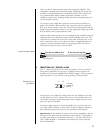
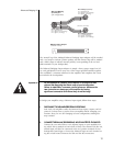
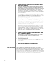
Modular cables and connectors are used throughout the world for both tele-
communications and computers, and are widely available at low cost. The
connectors are crimped on to the ends of the cable such that pin 1 at one
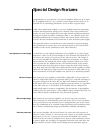
end is connected to pin 1 at the other end. Such a “straight-through” con-
nection is (counter-intuitively) made by introducing a 180° twist in the
cable between the two ends, as shown below.
communication cable
from Proceed PDSD or AVP To Five Channel Amplifier
Locking tabLocking tab
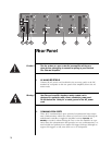
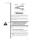
3 REMOTE TURN-ON (“TRIGGER’) JACKS
Two
1
⁄8" “mini” jacks above the AC mains receptacle on the rear panel al-
lows remote-controlled turn-on (that is, toggling between operate and
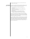
standby) of the Proceed amplifier. These remote “triggers” will be operated
by the presence of 5–12 volts DC, with tip polarity as shown below:
Remote turn-on
tip polarity
+–
5-12 volts,
positive tip
polarity
The presence of a suitable DC voltage will cause the amplifier to be fully
on; the absence of such a voltage will cause it to enter standby. Your Pro-
ceed dealer can help you take advantage of these design features to maxi-
mize your system’s versatility.
Since these trigger inputs are wired in parallel, you can go into one and
out of the other to facilitate a “daisy-chain” of turn-on triggers (should you
have additional products that need to be controlled in this manner).
Special note: if this method of control is used for the amplifier(s), the last
mini-jack in the chain must be terminated with a dummy
1
⁄8" plug [that is,
an empty plug must be inserted into the final
1
⁄8" (3.5 mm) jack]. Even if
only a single amplifier is controlled in this fashion, the “extra” mini-jack
must be terminated.