


10
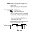
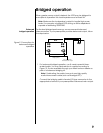
Figure 10: Balanced
bridging cable
21
3
21
3
Signal ground (shield)
Left-channel
XLR male
line-mount
(rear view)
Twisted pair
Right-channel
XLR male
line-mount
(rear view)
12
3
XLR female
line-mount
(rear view)
Twisted pair
Signal ground
(shield)
2. Connect the bridging cable's male XLR-type connectors to the
Nº29's left- and right-channel XLR-type input connectors, taking
care to insert the correct cable end into its designated channel.
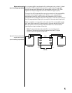
3. Connect the left-channel + (positive or red) output post of the
Nº29 to the + (positive or red) input terminal of the appropriate
loudspeaker. Connect the right-channel + (positive or red) output
post of the Nº29 to the – (negative or black) input terminal of the
same loudspeaker.
4. Repeat this procedure for the other Nº29 to be bridged.
If your preamplifier provides only single-ended output, follow the steps
below.
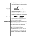
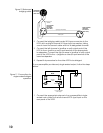
Figure 11: Connections for
single-ended bridged
operation
PUSHPUSH
+ – – +
– +
Loudspeaker
Nº29
From preamplifier
main output
Bridging
cable
Left
channel
1. Connect the appropriate channel of your preamplifier's single-
ended main output to the left-channel RCA-type input on the
rear panel of the Nº29.