


3
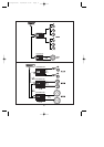
CONTROLS AND INDICATORS
10 • GND CONNECTOR for EXTERNAL CONDENSER: connect it directly to the negative
pole of a (1 or 1.5) FARAD condenser of 24CARAT PE1.0 or PE1.5 so that the amplifier’s
dynamic capacities are increased. (It is advisable to position the condenser as close as
possibile to the SYNTHESIS1000 amplifier).
NOTABENE: charge the condenser by means of the resistance included in the
packaging before connecting it to the amplifier.
11 • REMOTE IN/OUT CONNECTOR: IN should be connected to the remote switch-on output
lead or to the output lead of the power antenna coming from the head unit. By doing so the
SYNTHESIS1000 can be switched on and off through the head unit. Another amplifier can be
connected through OUT. If this is the case, one or more amplifiers can be switched on through
one connection to the head unit. (The OUT output is delayed compared to the remote ON
input).
12 • LOW PASS FREQUENCY ADJUSTMENT: allows continuous Low-Pass filter adjustment
13 • LOW PASS FILTER CROSSOVER SLOPE SELECTOR: allows to select the Low-Pass
filter crossover slope in the 12dB/Oct-24dB/Oct range; when set at the 24dB position ONLY ,
both internal and external Low-Pass filter configuration switches automatically to the MONO
configuration.
14 • HIGH PASS FREQUENCY ADJUSTMENT: allows continuous High-Pass filter
adjustment.
15 • EXTERNAL FILTER SELECTOR SWITCH (Flat-HI-LOW): allows to select the desired
type of filter either to connect externally a further amplifier or to disable the filter itself.
16 • INTERNAL FILTER SELECTOR (Flat-HI-LOW): allows to select the desired type of filter
either to connect externally a further amplifier or to disable the filter itself.
17 • LEFT INPUT GAIN ADJUSTMENT CONTROL: allows to adjust the input sensitivity of
the left channel only. It ranges from 0.2 mV to 8V.
If the amplifier is to be connected to a head unit that is fitted with preamplified RCA outputs,
proceed as follows:
a) set the volume control of your unit to 3/4 of maximum output level;
b) set the input gain control to the point where the maximum sound level with no distortion is
obtained.
18 • RIGHT INPUT GAIN ADJUSTMENT CONTROL: allows to adjust the input sensitivity of
the right channel only. It ranges from 0.2 mV to 8V.
If the amplifier is to be connected to a head unit that is fitted with preamplified RCA outputs,
proceed as follows:
a) set the volume control of your unit to 3/4 of maximum output level;
b) set the input gain control to the point where the maximum sound level with no distortion is
obtained.
19 • SENSITIVITY RANGE SELECTOR: allows to select the sensitivity range that is most
suitable to the unit installed.
20 • INPUT MODE SELECTOR: allows to select the amplifier’s configuration as follows:
a) STEREO “ST” when the amplifier is used as a two-channel stereo system (right + left);
b) MONO (L mono) when the amplifier is driven by one input signal “Left” and outputs are
mono-bridged.
O/M Synt1000 26/06/02 9:54 Page 3