SRM1850 • SRM2850 Powered Subwoofers
8
SRM1850 • SRM2850 Powered Subwoofers
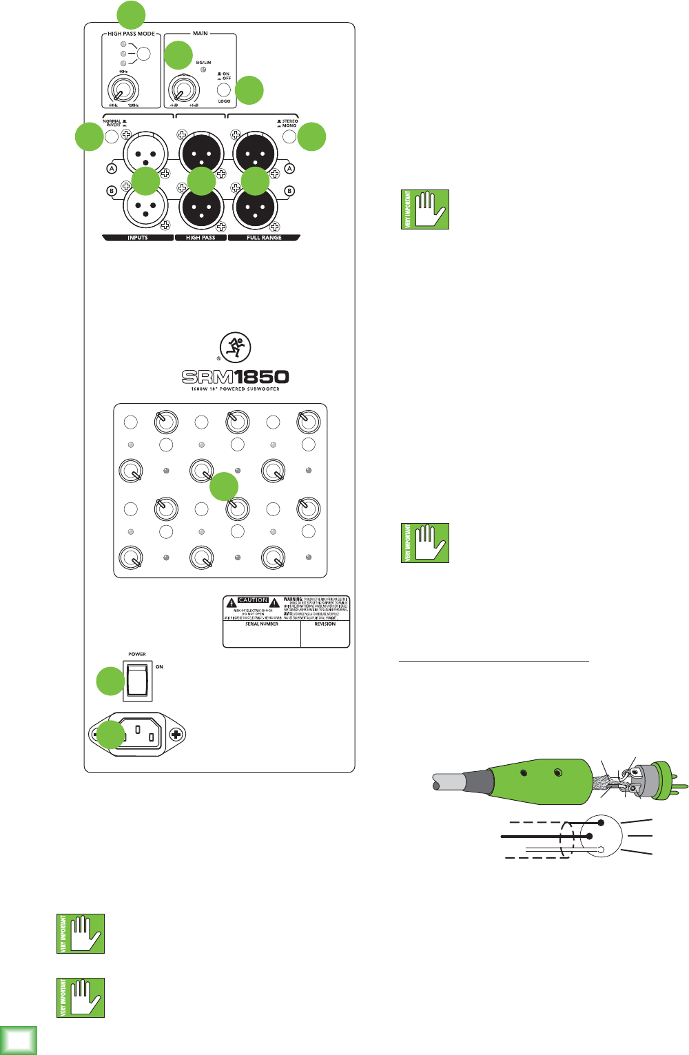
SRM Subwoofer: Rear Panel Features
1. Power Connection
Thisisastandard3-prongIECpowerconnector.
Connectthedetachablepowercord(includedin
thepackagingwiththesubwoofer)tothepower
receptacle,andplugtheotherendofthepower
cordintoanACoutlet.
MakesurethattheACpowerismatchedto
theACpowerindicatedontherearpanel
(belowtheIECreceptacle).
Disconnectingtheplug’sgroundpinis
dangerous.Don’tdoit!
2. Power Switch
Pressthetopofthisrockerswitchinwardstoturnon
thesubwoofer.ThefrontpanelRunningManlogowill
glowwithhappiness...oratleastitwillifthesubwoofer
ispluggedintoasuitableliveACmainssupplyandthe
mainlogoswitch[10]isdisengaged.
Pressthebottomofthisrockerswitchinwardstoturn
offthesubwoofer.
Asageneralguide,themixer(orothersignal
source)shouldbeturnedonrst,SRM
subwoofersnext,andloudspeakerslast.
Assuch,theloudspeakersshouldalsobeturnedoffrst,
followedbythesubwoofers,thenthemixer.Thiswill
reducethepossibilityofanyturn-onorturn-offthumps
andothernoisesgeneratedbyanyupstreamequipment
fromcomingoutofthespeakers.
3. XLR Inputs
BalancedXLRfemaleconnectorsareprovidedforthe
leftandrightinputs.Connectthefull-rangeline-level
signalfromthemixer(orothersignalsource)tothese
inputjacks.
Ifyouareconnectingasinglesubwooferoutput,or
LFE(low-frequencyeffects)outputtothesubwoofer,
youmayuseeithertheAorBinputconnector.
NEVERconnecttheoutputofanamplier
directlytotheinputofthesubwoofer.
Thiscoulddamagetheinputcircuitryofthe
activesubwoofer.
Theyarewiredasfollows,accordingtostandards
speciedbytheAES(AudioEngineeringSociety):
Balanced XLR Input Connector
Pin1–Shield(ground)
Pin2–Positive(+orhot)
Pin3–Negative(–orcold)
Formoreinformationontheseconnectors,see
AppendixBonpage14.
2
3
1
SHIELD
COLD
HOT
SHIELD
COLD
HOT
3
2
1
Balanced XLR Input Connector
SRM
550
SRM
650
VAR
POWER CONSUMPTION 200W
1
2
3
4 8
6
10
11
9
5
7


