


O F 8 P A G E S
M•1400/M•1400i
High-Current Power Amplier
AMPLIFIER
M•1400/M•1400i
M•1400/M•1400i
High-Current Power Amplier
O F 8 P A G E S
AMPLIFIER
M•1400/M•1400i
M•1400/M•1400i
High-Current Power Amplier
1
O F 8 P A G E S
AMPLIFIER
M•1400/M•1400i
O F 8 P A G E S
M•1400/M•1400i
High-Current Power Amplier
AMPLIFIER
M•1400/M•1400i
(continued from page 6)
7
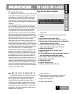
selecting limiter on, limiter off, and subwoofer mode. The
defeatable electronic limiter circuit shall sense the onset
of clipping and shall limit the input signal and thereby
prevent the output from clipping. The amplier shall have
a two-way switch appearing on the rear panel for select-
ing between a 63Hz and 125Hz low-pass cutoff frequency
when subwoofer mode is selected.
11. LOW-CUT FILTER. Each channel shall have a low-
cut lter with a variable frequency control appearing on
the rear panel covering a range of 10Hz (OFF) to 170Hz.
12. CONSTANT DIRECTIVITY HORN EQ. Each chan-
nel shall have a two-way switch appearing on the rear
panel for selecting a constant directivity horn equaliza-
tion circuit. When selected, this circuit shall provide a
6 dB per octave high-frequency boost. The EQ shall
have a variable frequency control appearing on the
rear panel covering a range of 2kHz to 6kHz. The
6kHz position shall be called AIR.
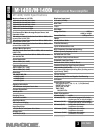
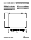
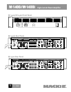
13. PHYSICAL CONFIGURATION. The amplier
shall be rack-mountable with rear support rails for
extra support, and shall have a steel chassis frame
painted gray-black. The amplier shall be 19" wide
(483mm), 3.5" (2U) tall (89mm), and 15.25" deep
(387mm), and shall weigh 36 pounds (16.3 kg).
14. DESIGNATION. The power ampliers shall be
a Mackie M•1400 and M1400i.
www.mackie.com
16220 Wood-Red Road NE, Woodinville, WA 98072 USA
800.898.3211, fax 425.487.4337, sales@mackie.com
UK +44.1268.570.808, fax +44.1268.570.809, uk@mackie.com