WARNING: Never attempt to suspend the
ART Series loudspeakers by their handles.
Consult a professional rigger or structural
engineer prior to suspending loudspeakers
from a structure not intended for that use.
Always know the working load limit of the
structure supporting the loudspeaker array.
Always make sure that the rigging hardware
minimum rating is at least five times the
actual load.
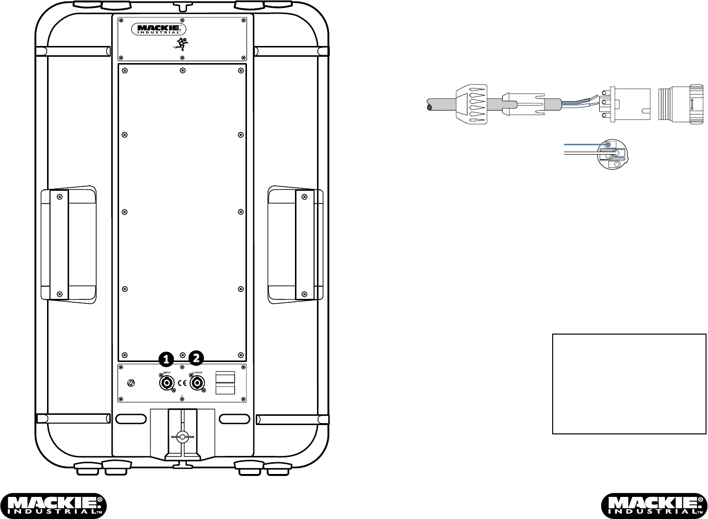
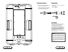
Rear Panel Features
1. INPUT is a Neutrik Speakon connector for
connecting a speaker-level signal.
2. OUTPUT is a Neutrik Speakon connector
that is paralleled with the INPUT jack, for
daisy-chaining speakers together.
Installation
A 1-3/8" (35mm) socket is provided in the
bottom of the cabinet for mounting the
loudspeaker on a speaker stand.
The ART500 can be suspended with
approved rigging hardware. Always use at
least two M10 threaded inserts located
on opposite sides of the enclosure. The
speaker must be positioned so that the
weight of the enclosure is equally distributed
over the two inserts.
Connections
The Speakon connectors use the following
wiring standard:
Pin 1+ = Signal (+)
Pin 1– = Ground (–)
COLD
HOT
1+
1+
1–
1–
2–
2+
ART 500
SPEAKER SYSTEM
THE FOLLOWING ARE TRADEMARKS/REGISTERED TRADEMARKS OF MACKIE DESIGN INC.: "MACKIE", "MACKIE INDUSTRIAL", & THE "RUNNING MAN" FIGURE
CONCEIVED, DESIGNED, AND MANUFACTURED BY MACKIE INDUSTRIAL • MADE IN ITALY • COPYRIGHT ©1999
ALL CONTACTS
PARALLEL WIRED
MANUFACTURING DATE
SERIAL NUMBER
(SIGNAL)
1+
(GROUND)
1–
2+
(N.C.)
2–
(N.C.)
IMPEDANCE: 8 POWER: 500W


