


INSTR, INSTL, XR-D
LINEAR P/N: 215170 B
MATERIAL: 20 LB. MEAD BOND
SIZE: 8.500" X 11.000"
SCALE: 1-1
INK: BLACK
SIDE 2 OF 2 (BACK)
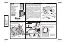
6. CONSTRUCT CABLE & CONNECT POWER 7. ASCII DATA OUTPUT DETAILS 8. MOUNT ANTENNA AND ROUTE CABLE
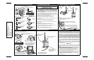
9. TEST SYSTEM 10. COMPLETE INSTALLATION LINEAR LIMITED WARRANTY
This Linear product is warranted against defects in material and workmanship
for twelve (12) months. The Warranty Expiration Date is labeled on the product.
This warranty extends only to wholesale customers who buy direct from Linear or
through Linear’s normal distribution channels. Linear does not warrant this product
to consumers. Consumers should inquire from their selling dealer as to the nature of
the dealer’s warranty, if any. There are no obligations or liabilities on the part of
Linear LLC for consequential damages arising out of or in connection with use
or performance of this product or other indirect damages with respect to loss of
property, revenue, or profit, or cost of removal, installation, or reinstallation. All
implied warranties, including implied warranties for merchantability and implied
warranties for fitness, are valid only until Warranty Expiration Date as labeled on the
product. This Linear LLC Warranty is in lieu of all other warranties express or
implied.
All products returned for warranty service require a Return Product Authorization
Number (RPA#). Contact Linear Technical Services at 1-800-421-1587 for an RPA#
and other important details.
IMPORTANT !!!
Linear radio controls provide a reliable communications link and fill an important need
in portable wireless signaling. However, there are some limitations which must be
observed.
✶ WARNING: THIS PRODUCT IS NOT TO BE USED IN LIFE SAFETY APPLICATIONS. FCC Rules allow
unlicensed high-power transmissions at or near the operating frequency of this product which may
interfere with, or even disable, normal operation of this radio device.
✶ For U.S. installations only: The radios are required to comply with FCC Rules and Regulations as Part 95
Radio Control devices. As such, they have limited transmitter power and therefore limited range.
✶ A receiver cannot respond to more than one transmitted signal at a time and may be blocked by radio signals
that occur on or near their operating frequencies, regardless of code settings.
✶ Changes or modifications to the device may void FCC compliance and user’s authority to operate equipment.
✶ Infrequently used radio links should be tested regularly to protect against undetected interference or fault.
✶ A general knowledge of radio and its vagaries should be gained prior to acting as a wholesale distributor or
dealer, and these facts should be communicated to the ultimate users.
Copyright © 2004 Linear LLC 215170 B
ANT-1A
ANTENNA
USE ANT-1A ANTENNA
FOR SHORT RANGE (LESS
THAN 1 MILE)
APPLICATIONS
CON-180A
STRAIGHT
CONNECTOR
CON-180A + CON-90A
ANGLE CONNECTOR
MOUNT ANTENNAS AS HIGH AS POSSIBLE
(A METAL MOUNTING POLE IS RECOMMENDED)
AN 18-FOOT RG-58 CABLE IS SUPPLIED WITH THE
ANT-2 KIT. UP TO 50 FEET OF RG-58 CAN BE USED.
USE RG-8 FOR UP TO 100-FOOT CABLE RUNS.
TO UNIT
USE 3-FOOT LONG ANT-2 ANTENNA FOR LONGER
RANGE APPLICATIONS OR DIFFICULT
INSTALLATIONS
GROUND
+12 VDC
DATA TERMINAL READY (DTR)
TRANSMIT DATA (TD)
SIGNAL GROUND (SIG GND)
GROUND
+ 12 VDC
TD
DTR
SIG GND
XR-D TO FEMALE DB-9 FOR COMPUTER CABLE
GROUND
+ 12 VDC
TD
DTR
SIG GND
XR-D TO FEMALE DB-25 FOR COMPUTER CABLE
GROUND
+ 12 VDC
TD
DTR
SIG GND
XR-D TO MALE DB-25 FOR PRINTER CABLE
GROUND
+ 12 VDC
TD
DTR
SIG GND
WARNING
THIS UNIT REQUIRES 12 VDC AT 1/2 AMP.
THE NO-LOAD VOLTAGE OF THE SUPPLY
MUST NOT EXCEED 17.5 VDC OR DAMAGE
TO THE UNIT WILL OCCUR!
ROUTE WIRES THROUGH
CASE STRAIN RELIEF
BUSHING BEFORE
CONNECTING TO TERMINALS
PIN 5 (SIG GND)
PIN 6 (DSR)
PIN 2 (RD)
PIN 7 (SIG GND)
PIN 6 (DSR)
PIN 3 (RD)
PIN 7 (SIG GND)
PIN 6 (DSR)
PIN 3 (RD)
FEMALE
DB-9
FEMALE
DB-25
MALE
DB-25
TRANSMITTER
RECEIVER
INSTALL AND SETUP THE TRANSMITTER AS
DESCRIBED IN ITS INSTALLATION INSTRUCTIONS
APPLY POWER AND TRIGGER THE
TRANSMITTER'S INPUT
THE TRANSMIT INDICATOR
SHOULD LIGHT WHEN THE
TRANSMITTER IS TRIGGERED
SEND MORE TEST TRANSMISSIONS, THE
RECEIVER'S SIGNAL INDICATOR SHOULD
LIGHT AS THE SIGNALS ARE RECEIVED (IF
LIT WITH NO SIGNALS, IT IS INTERFERENCE)
WARNING
NEVER CONNECT THE TRANSMITTER AND
RECEIVER ANTENNA CONNECTORS
DIRECTLY TO EACH OTHER. MAJOR
DAMAGE TO BOTH UNITS WILL OCCUR!
VERIFY THAT COMPUTER OR PRINTER
IS SETUP PROPERLY AND ACQUIRING
THE DATA FROM THE RECEIVER
(PRESSING THE RECEIVER'S TEST
BUTTON WILL ALSO SEND DATA)
1
2
3
SLIDE RECEIVER
BOARD INTO CASE IN
THE 3RD SLOT UP
BAUD RATE: 9600
STOP BITS: 1
PARITY: NONE
SECURE END PLATE BY
INSTALLING THE FOUR
CASE SCREWS
TIGHTEN WIRING STRAIN
RELIEF BUSHING TO
SECURE AND WEATHER
PROOF WIRING
INSTALL THE TWO REMAINING
MOUNTING SCREWS
TEST SYSTEM AGAIN AFTER
COMPLETING INSTALLATION
P SSSSSS CCCC BTARVXE
XR-D SERIAL DATA OUTPUT STRING KEY
DATA OUTPUT PRODUCED WHEN PRESSING XR-D TEST BUTTON
A 65432 0001 21A0HX
P = PACKET TYPE CHARACTER (A OR B). XT TRANSMITTERS SEND FOUR ROUNDS
OF DATA EACH ACTIVATION. PACKET TYPE "A" IS FIRST ROUND, PACKET TYPE "B"
IS FOR THE NEXT THREE ROUNDS.
S = FIVE-DIGIT DECIMAL NUMBER (00000 - 65535) THAT IS EQUAL TO THE BINARY
CODE SET ON THE TRANSMITTER'S SYSTEM CODE SWITCHES "A" & "B" . SYSTEM
CODE SWITCH "B", POSITION 8 IS THE LEAST SIGNIFICANT BINARY DIGIT, SWITCH
"A" POSITION 1 IS THE MOST SIGNIFICANT BINARY DIGIT.
C = FOUR BINARY DIGITS (0 OR 1) INDICATING TRANSMITTER CHANNEL
ACTIVATED. 0=NO ALARM, 1=ALARM. ORDERED CH4, CH3, CH2, CH1.
B = ONE-DIGIT DECIMAL NUMBER (0 - 3) EQUAL TO THE BANK NUMBER (1-4) SET IN
THE TRANSMITTER.
T = ONE-DIGIT DECIMAL NUMBER (0 - 2) DEFINING TRANSMITTER TYPE
(0 = XT-1, 1 = XT-4, 2 = XT-2H OR XT-4H IN MULTI-CHANNEL MODE).
A = ALARM/RESTORE CHARACTER (A OR R). RELEVANT FOR SINGLE-CHANNEL
TRANSMITTERS ONLY.
R = ONE-DIGIT BINARY DIGIT (0 OR 1) INDICATING THE STATE OF THE
TRANSMITTER'S AUTO-RESTORE SWITCH (0 = OFF, 1 = ON).
V = TRANSMITTER VOLTAGE CHARACTER (H OR L). NORMAL CONDITION = "H". IF
TRANSMITTER VOLTAGE IS BELOW 10.5 VDC CHARACTER = "L".
X = SPARE CHARACTER, NOT IMPLEMENTED AT THIS TIME.
E = END-OF-DATA. A CARRIAGE RETURN AND A LINE FEED ARE SENT.