


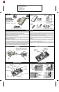
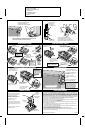
DXS-31 Installation Instructions
Linear P/N: 212790 B
Material: 20 Lb. Mead Bond
Size: 8 1/2 x 11"
Ink: PMS 561 (Aqua)
2 of 2 (Back Side)
Scale: 1-1
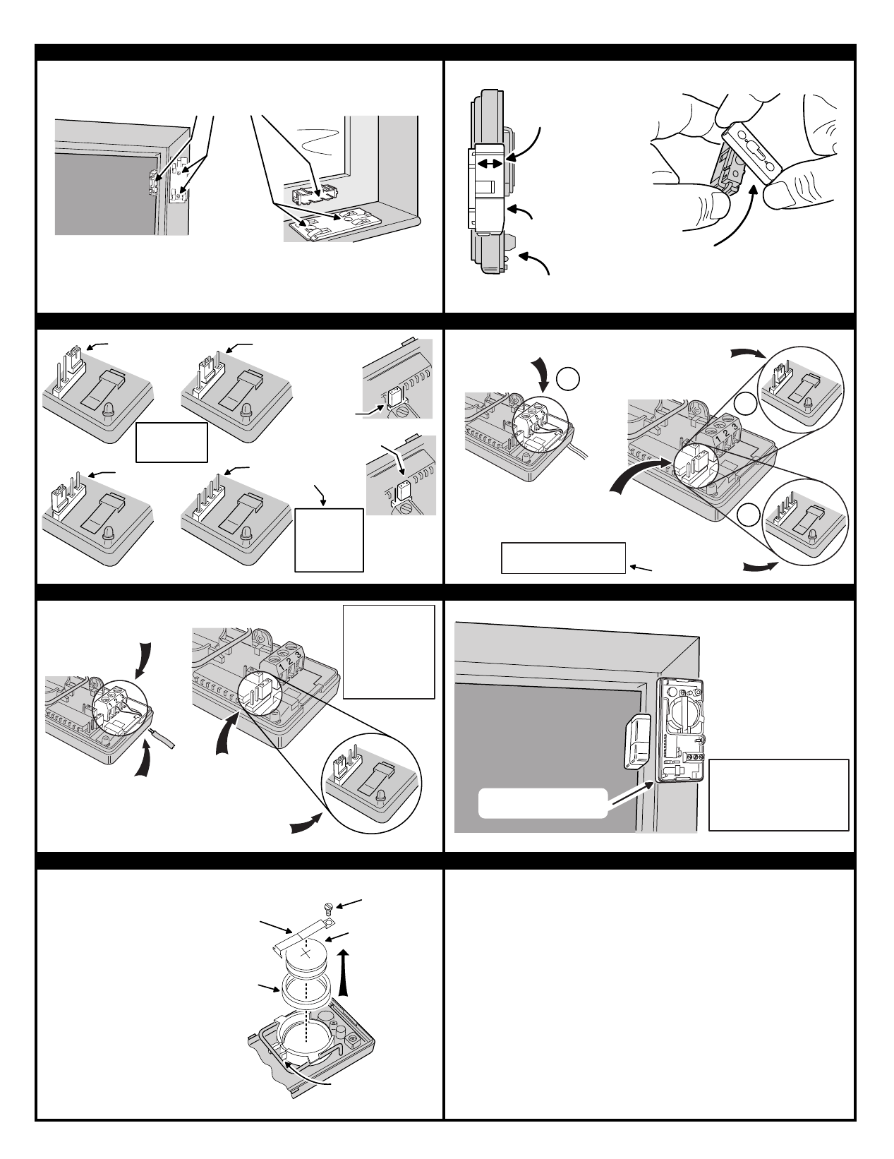
TRANSMITTER MOUNTING ADJUSTING MAGNET HEIGHT
OPTION JUMPER POSITIONS CONNECTING EXTERNAL CONTACTS
CONNECTING EXTERNAL GLASS BREAK SENSOR PROGRAMMING RECEIVER
CHANGING BATTERIES LINEAR LIMITED WARRANTY
This Linear product is warranted against defects in material and workmanship for twelve (12) months. The Warranty Expiration Date
is labeled on the product.
This warranty extends only to wholesale customers
who buy direct from Linear or through Linear’s
normal distribution channels.
Linear does not warrant this product to consumers.
Consumers should inquire from their selling
dealer as to the nature of the dealer’s warranty, if any.
There are no obligations or liabilities on the part of Linear corporation
for consequential damages arising out of or in connection with use or performance of this product or other indirect damages
with respect to loss of property, revenue, or profit, or cost of removal, installation, or reinstallation.
All implied warranties,
including implied warranties for merchantability and implied warranties for fitness, are valid only until Warranty Expiration Date as
labeled on the product.
This Linear Corporation Warranty is in lieu of all other warranties express or implied.
For warranty service on Linear equipment return product, at sender’s expense to:
All products returned for warranty service require a Return Product Authorization Number (RPA#). Contact Linear Technical Services
at 1-800-421-1587 for an RPA# and other important details.
IMPORTANT !!!
Linear radio controls provide a reliable communications link and fill an important need in portable wireless signalling. However, there
are some limitations which must be observed.
✶
For U.S. installations only: The radios are required to comply with FCC Rules and Regulations as Part 15 devices. As such,
they have limited transmitter power and therefore limited range.
✶
A receiver cannot respond to more than one transmitted signal at a time and may be blocked by radio signals that occur on or
near their operating frequencies, regardless of code settings.
✶
Changes or modifications to the device may void FCC compliance.
✶
Infrequently used radio links should be tested regularly to protect against undetected interference or fault.
✶
A general knowledge of radio and its vagaries should be gained prior to acting as a wholesale distributor or dealer, and these
facts should be communicated to the ultimate users.
Copyright © 1997 Linear Corporation 212790 B
ATTACH MOUNTING PLATES
USING THE SCREWS OR
DOUBLE-STICK TAPE PROVIDED
NOTE: ATTACHING THE TRANSMITTER WITH DOUBLE-STICK
TAPE IS NOT ALLOWED IN UL INSTALLATIONS
ADJUST MAGNET
HEIGHT UNTIL
CASE LEVELS
ARE ABOUT EQUAL
TRANSMITTER
CASE BOTTOM
MAGNET
THE SNAP-ON MAGNET SPACER
CAN BE USED TO ADD 1/4" HEIGHT
TO THE MAGNET (SPACERS CAN ALSO
BE SNAPPED TOGETHER FOR MORE LIFT)
SELECTS INTERNAL
SWITCH
(INSIDE POSITION)
SELECTS GLASS
BREAK SENSOR ONLY
(EDGE POSITION)
SELECTS EXTERNAL
SWITCH
(MIDDLE POSITION)
SELECTS BOTH
INTERNAL AND
EXTERNAL SWITCHES
(NO JUMPER)
NOTE: THE TWO
SWITCHES
ARE IN SERIES,
BOTH MUST BE
CLOSED TO
RESTORE LOOP
NOTE: GLASS
BREAK INPUT
TERMINALS ARE
ALWAYS ACTIVE
INPUT SELECT
JUMPER
INSTANT/
DELAY
SELECT
JUMPER
SELECTS
DELAY
SELECTS
INSTANT
CONNECT NORMALLY OPEN
GLASS BREAK SENSOR
WIRES TO TERMINALS 2 & 3
ROUTE SENSOR WIRES UP
THROUGH WIRING SLOT
NOTE: THIS
TRANSMITTER IS
DESIGNED FOR USE
WITH THE UNITED
SECURITY PRODUCTS
"WINDOW BUG" GLASS
BREAK SENSOR.
OTHER SENSORS
HAVE NOT BEEN
TESTED.
REMOVE JUMPER FROM
THESE PINS (SELECTS
INTERNAL SWITCH)
PLACE JUMPER ON THESE
PINS (SELECTS GLASS
BREAK SENSOR)
1. PLACE RECEIVER INTO
PROGRAM OR "LEARN" MODE
2. ACTIVATE TRANSMITTER
BY OPENING DOOR OR
WINDOW
3. VERIFY THAT THE
RECEIVER ACCEPTED THE
SIGNAL
4. REPLACE TRANSMITTER
COVER WHEN FINISHED
NOTE: THE TRANSMIT
INDICATOR WILL ONLY LIGHT
DURING TRANSMISSIONS
WHEN THE CASE IS OPEN
(EXCEPT WHEN PUSHING
THE CASE FOR TESTING)
OPEN DOOR, TRANSMIT
INDICATOR SHOULD LIGHT
WIRE EXTERNAL NORMALLY
CLOSED CONTACTS TO
TERMINALS 1 & 2
THIS IS THE FACTORY SET
JUMPER POSITION, IT
SELECTS THE INTERNAL
CONTACTS
PUT JUMPER ON THE
MIDDLE PINS TO USE
AN EXTERNAL SWITCH
- OR -
REMOVE JUMPER TO USE
BOTH EXTERNAL AND
INTERNAL SWITCHES
(SEE NOTE)
2A
2B
1
NOTE: THE TWO SWITCHES
ARE IN SERIES, BOTH MUST BE
CLOSED TO RESTORE LOOP
REDUCTION
RING
BATTERY
CLAMP
TWO TYPE 2032
BATTERIES
BATTERY
RETAINING
SCREW
SLIDE "T" END
OF CLAMP
THROUGH SLOT
WHEN THE TRANSMIT INDICATOR
BLINKS DURING TRANSMISSIONS
OR WHEN THE RECEIVER
INDICATES A LOW BATTERY, THE
BATTERIES NEED REPLACING
1. REMOVE THE BATTERY
RETAINING SCREW
2. REMOVE THE BATTERY CLAMP
3. REPLACE BATTERIES WITH TWO
TYPE 2032 BATTERIES (PLUS SIDE
UP)
4. REPLACE BATTERY CLAMP AND
RETAINING SCREW