


Channel 1 on the receiver is selected by moving the 10th position of the transmitter
side A to the off (open) position. Channel 2 is selected by moving the 10th position
of the transmitter side B to the on (closed) position. Once the codes have been set,
check the operation and replace the lower cover.
TRANSMITTER INSTALLATION
The transmitter is completely self contained, including battery, and can be operated
while mounted in the car. It is supplied with a clip for attaching to the sun visor, if
desired. If the clip is used, attach to the case by sliding it into the recess provided
on the back of the transmitter until the small dimples fi t into the holes in the clip.
WARRANTY
ALL MULTI-CODE door related products carry a eighteen (18) month warranty
against defects in workmanship or material. This warranty begins at the date of
manufacture, for eighteen months. Linear LLC warranties our product only to our
authorized dealers and distributors, and not to the end customer. If you have nay
questions about our warranty, please ask your dealer to determine the nature and
scope of his warranty. Linear LLC does not assume, and is not responsible for,
any real or consequential damages from claims against the performance of our
product, nor is it liable for any costs related to loss of life, property, or revenue.
Further, Linear LLC is in no way responsible for installation of our product, and will
assume no costs to reinstallation or removal. Linear LLC Warranty is in lieu of all
other warranties, expressed, or implied.
PRINTER’S INSTRUCTIONS:
INSTR,INSTL,MC4120,2 CH,TX - LINEAR P/N: 214881 B - INK: BLACK - MATERIAL: 20 LB. MEAD BOND - SIZE: 9.000” X 3.500” - SCALE: 1-1 - SIDE 2 OF 2
CODING
Before placing your transmitter into service, we urge you to set your codes, in
order not to interfere with neighboring systems, and to provide security for your
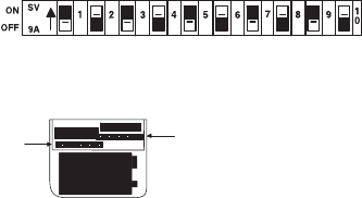
own system. You will note that the model 4120 transmitter has two, ten position
code switches (see fi gure 1). We strongly urge that several coding schemes be
avoided: ALL ON; ALL OFF; 2, 4, 6, 8, 10, ON; 1, 3, 5, 7, 9, ON. These positions
are similar to our or other manufacturer’s test positions, or are frequently used.
If you have two single channel receivers: Set your transmitter so that the ten
position switch on side A will match your receiver #1. Set the ten position switch
on transmitter side B to your receiver #2 (see fi gure 2).
If you have a MULTI-CODE™ 3021 or 3028 two channel receiver: Set the
receiver and transmitter (side A and B) code switch positions 1-9 to match. The
10th position on your transmitter code switches are used for channel selection.
CODE SWITCH
SIDE A
CODE SWITCH
SIDE B
Figure 2
Figure 1
CODE SWITCH