


- 6 -
BAttery And ChArging
Amplifiers will put an increased load on the vehicle's battery and charging system. We recommend checking your
alternator and battery condition to ensure that the electrical system has enough capacity to handle the increased load of
your stereo system. Stock electrical systems which are in good condition should be able to handle the extra load of any
Lightning Audio amplifier without problems, although battery and alternator life can be reduced slightly. To maximize the per-
formance of your Lightning Audio amplifier, we suggest the use of a heavy duty battery and an energy storage capacitor.
CAUTION: Avoid running power wires near the low level input cables, antenna, power leads, sensitive equipment
or harnesses. The power wires carry substantial current and could induce noise into the audio system.
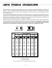
• For safety, disconnect the negative lead from the battery prior to beginning the installation.
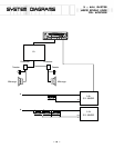
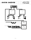
1. Plan the wire routing. Take care when running signal level RCA cables to keep them close together but isolated from
the amplifier's power cables and any high power auto accessories, especially electric motors. This is done to prevent
coupling the noise from radiated electrical fields into the audio signal. When feeding the wires through the firewall or
any metal barrier, protect them with plastic or rubber grommets to prevent short circuits. Leave the wires long at this
point to adjust for a precise fit at a later time.
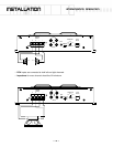
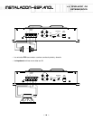
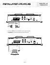
2. Prepare the Power cable for attachment to the amplifier by stripping 1/2" of insulation from the end of the wire. Insert
the bared wire into the B+ terminal and tighten the set screw to secure the cable in place.
NOTE: The B+ cable MUST be fused 18" or less from the vehicle's battery. Install the fuseholder under the hood
and prepare the cable ends as stated above. Connections should be water tight.
Trim the power cable within 18" of the battery and strip 1/2" of insulation from the end of the wire. Cut the wire loop
that is attached to the fuseholder in half and splice the fuse into the power line using appropriate inline con-
nectors. Use the section of cable that was trimmed earlier and connect it to the other end of the fuseholder.
3. Strip 1/2" from the battery end of the power cable and crimp a large ring terminal to the cable. Use the ring terminal to
connect to the battery positive terminal. Do not install the fuse at this time.
4. Prepare the Ground cable for attachment to the amplifier by stripping 1/2" of insulation from the end of the wire. Insert
the bared wire into the GND terminal and tighten the set screw to secure the cable in place. Prepare the chassis ground
by scraping any paint from the metal surface and thoroughly clean the area of all dirt and grease. Strip the other end of
the wire and attach a ring connector. Fasten the cable to the chassis using a non-anodized screw and a star washer.
5. Prepare the REM turn-on wire for connection to the amplifier by stripping 1/2" of insulation from the wire end. Insert
the bared wire into the REM terminal and tighten the set screw to secure the cable into place. Connect the other end
of the REM wire to a switched 12 volt positive source. The switched voltage is usually taken from the source unit's auto
antenna or the accessory lead. If the source unit does not have these outputs available, the recommended solution is
to wire a mechanical switch in line with a 12 volt source to activate the amplifier.
6. Securely mount the amplifier to the vehicle or amp rack. Be careful not to mount the amplifier on cardboard or plastic
panels. Doing so may enable the screws to pull out from the panel due to road vibration or sudden vehicle stops.
7. Connect the source signal to the amplifier by plugging the RCA cables/high level inputs into the input jacks at the amplifier.
8. Connect the speakers. Strip the speaker wires 1/2" and insert into the speaker terminal and tighten the set screw to
secure into place. Be sure to maintain proper speaker polarity. DO NOT chassis ground any of the speaker leads
as unstable operation may result.
9. Perform a final check of the completed system wiring to ensure that all connections are accurate. Check all power and
ground connections for frayed wires and loose connections which could cause problems.
Wiring the System