


User Manual
3. Operating Instructions (contd.)
© LA Audio 2004
12
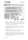
5. Shelving Filter Bypass switch allows the filter to be taken out of circuit. This
allows you to hear its effects when compared to the unfiltered sound, and also
to allow low frequencies to pass unaffected.
6. Shelving Filter Frequency rotary potentiometers enable control of the LF and
HF shelf frequency.
7. Shelving EQ section faders enable control of the amount of cut or boost, a
centre detent is provided at 0dB.
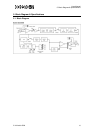
8. The High-pass filter is a 4th order design (24dB/octave) with the corner
frequency variable from 16 Hz to 160 Hz. The Lo-pass filter is a 2nd order
design (12dB/octave) with the corner frequency variable from 3KHz to 32KHz.
9. The Dynamics Bypass switch allows the whole section to be taken out of
circuit.
10. The Dynamics section features a Limiter and a Gate. The Gate Threshold
potentiometer controls the level of signal necessary to turn on the gate. Below
this level, the signal is attenuated in such a way that unwanted noises such as
hiss and hum are reduced. The Gate LED illuminates when the signal is below
threshold, indicating the gate is "closed".
11. The Limiter Threshold potentiometer controls the level above which gain is
reduced in order to keep the level constant, thus avoiding damage to
succeeding equipment. A 3 LED progressive luminosity bargraph indicates the
gain reduction or "amount of limiting". The Threshold ranges of the Gate and
Limiter are such that in the extreme positions (Gate at -70dB, Limiter at +20)
they can be considered out of circuit.
12. The Phase Reverse switch reverses the connections of the output XLR
connectors. This passive arrangement guarantees that, even when the unit is
off, the phase condition is retained. A red LED illuminates to indicate the
Reverse condition.