


KRAMER: SIMPLE CREATIVE TECHNOLOGY
Your RC-2C/RC-2
6
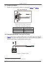
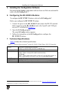
4.1 The RS-232 PINOUT
The RS-232 9-pin D-sub port PINOUT is defined in
Figure 4 and Table 3:
RS-232 PINOUT
Rx
GND
1
2
3
4
5
6
7
8
9
Tx
Figure 4: RS-232 PINOUT Connection
Table 3: RS-232 PINOUT Connection
Connect this PIN on the
Terminal Block Connector:
To this PIN on the
9-pin D-sub Connector
Tx PIN 2
Rx PIN 3
GND PIN 5
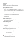
4.2 Connecting the IR-OUT (for the RC-2C Only)
Figure 5 shows how to connect the IR emitter
1
. The white striped side connects
to IR OUT, the black side connects to the Ground, and the LED Emitter Shell is
affixed to the IR sensor window with the adhesive layer.
Figure 5: IR Emitter Wiring
1 Using the Kramer 3.5mm to IR Emitter Control Cable (C-A35/IRE-10)