


8
PT-571HDCP/PT-572HDCP+ - Connecting the Transmitter Receiver Pair
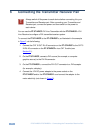
6 Connecting the Transmitter Receiver Pair
Always switch off the power to each device before connecting it to your
Transmitter and Receiver pair. After connecting your Transmitter and
Receiver pair, connect the power and then switch on the power to
each device.
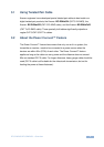
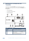
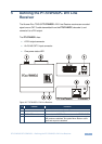
You can use the PT-571HDCP DVI Line Transmitter with the PT-572HDCP+ DVI
Line Receiver to configure a DVI transmitter/receiver system.
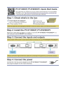
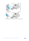
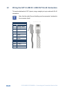
To connect the PT-571HDCP to the PT-572HDCP+, as illustrated in the example
in Figure 3, do the following:
1. Connect the CAT 5 OUT RJ-45 connector on the PT-571HDCP to the CAT 5
IN RJ-45 connector on the PT-572HDCP+ via a CAT 5 cable (see
Section 6.1).
2. On the PT-571HDCP, connect a DVI source (for example, a computer
graphics source) to the DVI IN connector.
3. On the PT-572HDCP+, connect the DVI OUT connector to a DVI acceptor
(for example, a display).
4. Connect the 12V DC power adapter to the power socket on the
PT-571HDCP and/or the PT-572HDCP+ and connect the adapter to the
mains electricity (not shown in Figure 3).
!