


under 500’ and 20-gauge for runs up to 1000’. Wires can be
looped from IR230 to IR230 or home run. Home runs generally
offer more reliability and future flexibility.
4. IR230s can be mixed and matched in larger systems with up
to 10 infrared receivers, such as the Knoll IR100 or IR220.
5. Drill a ½” (12 mm) in any flat surface such as a door. Pass
the lead and the body of the IR230 through the hole. Screw on
the brass or white bezel. Next secure the IR230 with the nut
provided. Do not over tighten the nut.
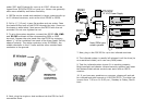
5. To wire the system together, connect the IR230 12V, GND
and IR SIG terminals to the corresponding IR54 or IR55
terminal. Prepare the wire leads from the IR230 by stripping
about ¼” of the insulation from each of the three leads. Strictly
observe polarity. The white conductor is the IR SIGNAL, the
middle conductor is the 12 volts and the other outside black
conductor is the ground.
6. Next, plug the single or dual emitters into the IR54 or IR55
connection block.
7. Now, plug in the PS1205 for up to ten infrared receivers.
8. The infrared system is usually left plugged in all the time (to
an unswitched outlet) as it uses very little power.
9. Test the infrared system to see if it is working properly.
Bright sunlight and passive infrared security systems can lower
the distance that remote controls can work with an IR230
receiver.
10. If you have any questions or concerns, please call and ask
for infrared technical support at 1 800 566 5579. The Help Line
is open from 7:30 a.m. to 5:00 p.m., Monday to Friday, Pacific
time.
Receiver
CD
IR31A
IR34A
IR55
PS1202
12 V DC Power Supply
Dish
IR34A
171
Connection
Block
Note: IR23a’s are
wired in parallel
12V
GND
SIG
White
Wire
Panel
nut
Bezel
IR230
White
Wire
IR230