


speaker cones will be moving in, while others move out. This
will cause indistinct or confusing imaging, and muddled and
cloudy sounds. To avoid incorrect phasing or polarity, be sure to
use wire that has distinct markings, colors, stripes, wording, or
grooves on each side of the speaker cable. When making
connections to the amp and speakers, follow a consistent
pattern of using one side of the wire to the red terminals and
the other side to the black. When using cable with markings on
one side only, standard convention is to consider the marked
side of the wire as the red, or positive (+) connection, and the
non-marked side as the black or negative (-) connection.
Next loosen the knobs of the amplifier’s speaker output
terminals far enough so that they pass through hole is revealed.
Follow the proper connection instruction for your system with
regard to which terminals are used. Once the connections are
made, twist the cap back so that the connection is secured but
do not over tighten or use tools, as this may break the delicate
wire strands and decrease system performance.
If you are using spade lugs, connect them to the speaker wire
using the manufacturer’s instructions, and then loosen the caps
on the speaker terminals. Place lugs between the plastic cap
and the back of the terminal. Be sure to observe proper polarity.
Use your fingers to tighten to obtain a positive contact.
When using banana plugs, connections may be made by
inserting the jack affixed to your speaker wire into the hole
provided on the rear of the colored screw caps on the binding
posts. Before using banana –type jacks, make certain that the
plastic screw caps are firmly tightened down by turning them in
a clockwise direction until they are snug against the chassis.
This ensures that the maximum surface area of the plug is in
contact with the jack. Watch for proper polarity.
Run the cables to speaker locations. Do not coil any excess
cable, as this may become an inductor that creates frequency
response variations in your system. Lastly, connect the wires to
the speakers, again being aware of proper polarity. Remember
to connect the negative, or black wire, to the matching terminal
on the speaker. The positive or red wire should be connected to
the matching terminal on the speaker.
Note: While most speaker manufacturers follow industry convention of using
red terminals for positive connections and black terminals for negative, some
manufacturers may vary from this configuration. To ensure proper phase
connections, and optimal performance, consult the identification plate on our
speaker terminals, or the speaker’s manual to verify polarity. Contact the
speaker’s manufacturer if you do not know the polarity of your speakers.
Making rear panel connections
When connecting the amplifier to your source equipment, match
the output channel designations on the rear of your source
equipment to the input jacks on the rear panel of your amplifier
that have the same channel name. Correct polarity connections
are important to maintain proper speaker phasing. When
making connections to the amp and speakers, follow a
consistent pattern of using one side of the wire to the red
terminals and the other side to the black terminals.
Power control connections
The 21k amplifier features a built-in remote turn-on system that
can automatically switch the amplifier on when another device
in the system is switched on.
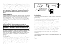
Remote turn-on using products equipped with a low-
voltage trigger jack: Make sure the 21k front panel power
switch is in the out of “OFF” position. Use an accessory cable
with a 3.5mm mono mini-plug on each end to connect the
trigger output jack on the rear of the source device to the
trigger input jack on the back panel of the amplifier. The trigger
needs to be 12 VDC and about 35 mA. When trigger power is
switched on, the amplifier will automatically turn on at the same
time.
Remote turn-on using external AC to DC power converter:
If your source device does not have a dedicated trigger jack, it
is still possible to activate the unit for automatic turn on when a
Switched Outlet is available on the rear of the source device. To
control the 21k amplifier this way, you will need a small AC to
DC power converter like our PS1202, capable of delivering 12
volts DC and over 35 mA. The DC voltage should terminate in a
standard 3.5mm type mini plug (this will have to be added to
the PS1202). This type of converter may be obtained as a power
adapter from many electronic retailers.