


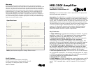

Knoll Systems service information Installation
Installing the MR1250f should be relatively easy. With a bit of
planning, the
MR1250f will give trouble free service for years.
The MR1250f amplifier does not contain any user serviceable parts
inside. If you suspect a problem that may require servicing, contact us
at www.knollsystems.com/contact.html, or by phone at 800 566-5579.
1. The most important consideration when installing the
MR1250f is cooling. The
MR1250f has a lot of power packed
into a small chassis size. When installing it in an equipment
stack, it should be the top component. It needs at least 3"-5" of
space above the amplifier to allow for adequate convection
cooling.
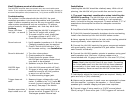
Troubleshooting
If a problem is encountered with the
MR1250f, the most
expedient procedure is to locate the problem and if possible
repair it before requesting service. Be sure to carefully check
other system components such as controllers, CD players,
volume controls, wiring, speakers, etc. that may be at fault.
Problem Action
2. Amplifiers should always be the top components in system.
Power LED does 1. Check that the
MR1250f is plugged in.
not light - no sound 2. Test the AC outlet with a lamp.
3. If
MR1250f channels frequently shutdown due to overheating,
install a fan directed up from the
MR1250f bottom center.
3. If remote on/off is used, check that
the trigger voltage is at 12 VDC.
4. Check
MR1250f power button on (in).
4. Never operate the
MR1250f on its side, as the cooling potential
drops significantly when operated on the side.
Sound cuts out 1. Verify speaker impedance is 4-16 ohms.
Changing speakers may be required.
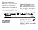
5. Connect the
MR1250f inputs to the source component outputs
with good quality, short as possible RCA jack cables. Connect
each channel individually.
2. Check if the
MR1250f feels hot. If it's
hot increase cooling - see Installation.
Sound is distorted 1. Turn the volume down.
6. Connect the
MR1250f speaker outputs to speakers using good
quality speaker wire. Minimum 16 gauge copper wire is
recommended with 14 gauge minimum for runs over 30' (10m).
2. Check speakers for damage.
3. Check inputs for proper levels.
MR1250f gain and source output level
may have to be adjusted.
Note: Ideally the
MR1250f likes 6-8 ohm loads. Connecting
4. Speakers may be less than 4 ohms.
to 4 ohm loads won't hurt the
MR1250f but those channels
connected to 4 ohm loads may occasionally shutdown due
MA1250 does 1. Push
MR1250f power switch off (out)
to overloading. Never connect the
MR1250f to less than 4
not turn off 2. If trigger is being used, power switch
ohms.
needs to be set to off (out) position
or amp is on all the time.
7. Individually adjust the channel gains as required. Ideally, all
gains are fully on (fully clockwise).
3. Try disconnecting trigger jack.
Trigger does not 1. Measure trigger voltage with a volt
8. Make sure the speakers in each room are connected in phase
with the amplifier + going to the speaker + . Out of phase
speakers give unstable imaging and poor bass response.
work meter. It needs to be 11-15 volts DC
to work (current is about 35mA total
per amp). See page 5 for details.
9. Connect trigger if being used to a 12 VDC source (about
35mA) using a 3.5mm mono jack. 5 VDC triggers will not work.
Speaker pops when 1. Speaker may need resistor placed
amp turned on or off across terminal. Suggest 2k0 1/4 w.
Discharges speaker internal cap.