


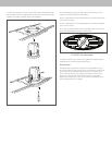

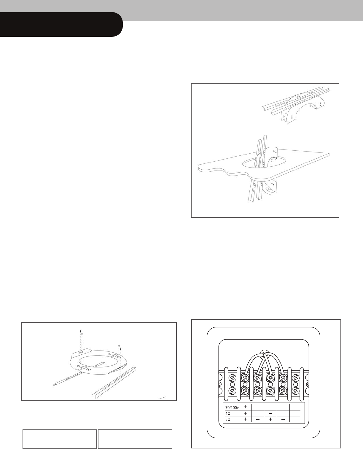
3. To install the tilebridge, fold the rail side of the ring back
upon itself using the spring tensioner on the reinforcement ring
to allow insertion into the cutout hole. Once it is inserted into
the cutout hole, release the reinforcement ring such that it
unfolds back to its normal position. Position tilebridge over
cutout hole.
4. The wiring compartment is intended as a termination point
for the audio circuit. Access to this compartment is gained by
removing the terminal cover located on the back of the
speaker. The terminal cover will accept the appropriate
conduit/wire adapter (provided). Feed wires through
conduit/wire adapter and connect to the input terminal
according to the desired operation mode. Be sure to observe
proper polarity. Replace the terminal cover and tighten the
conduit/wire adapter to secure the wire.
Caution: When connecting 70V or 100V distributed
line systems, take care to ensure proper terminal
connection. Connection to the low impedance termi-
nal could result in speaker damage, amplifier
damage, or both.
Thank you for purchasing your
Klipsch IC-SW-8T2 in-ceiling subwoofer.
The IC-SW-8T2 in-ceiling speaker is designed for music reinforce-
ment applications. Unobtrusive, these loudspeakers ar
e engi-
neered for easy, versatile installation.
The IC-SW-8T2 features a transformer-less design for 70.7V/100V
distributed-line systems. Some of the benefits of this design are:
Elimintation of transformer saturation at high output levels,
elimination of transformer insertion losses, improved bandwidth
(particularly at low frequencies), and improves power transfer to
the loudspeaker at low frequencies. For applications where 4
ohm mono or 8 ohm stereo operation is required, the mode of
operation can be selected by using an optional connection
located on the back input terminal and by properly setting the
rotary switch located under the grill.
Before installing your speakers take a moment to check the
contents of the cartons and make sure nothing has been
damaged in transit.
Contents Description Q
UANTITY
Speaker Module 1
Grille 1
Reinforcement Ring 1
Rails 2
Cardboard Cutout Template and Paint Mask 1
Screws (Attach Rails to Reinforcement Ring) 2
3/
8"
Adapter Fittings 1
1/
2"
Adapter Fittings 1
Installation Guidelines
The IC-SW-8T2 includes a tilebridge for use when installing
the loudspeaker into suspended ceilings or wher
ever additional
reinforcement of the ceiling material is required. The tilebridge
and loudspeaker are designed such that installation may be
accomplished where access above the ceiling is not possible
or may be difficult.
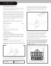
Installation
1.
The tilebridge is composed of three parts—a reinforcement ring
and two rails. The two rails should be attached to the
reinforcement ring using the two included screws as shown below.
Caution: Be sure to comply with any and all building codes
in your area.
2. To install your IC-SW-8T2 cut out a hole in the ceiling using
either the cardboard cutout template provided with your speak-
ers or consult the measurements below. Pull wiring through hole.
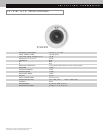
IC-SW-8T2
IC-SW-8T2 12.5 "Round