


Installation
1. Mounting Choose a structurally sound location to mount your Kicker amplifi er. Make sure there
are no items behind the area where the screws will be driven. Choose a location that allows at least
4” (10cm) of open ventilation for the amplifi er. If possible, mount the amplifi er in the climate-controlled
passenger compartment. Drill four holes using a 7/64” (3mm) bit and use the supplied #8 screws to
mount the amplifi er.
2. Wiring Disconnect the vehicle’s battery to avoid an electrical short. Then, connect the ground wire to
the amplifi er. Make the ground wire short, 24” (60cm) or less, and connect it to a paint and corrosion free
solid metal area of the vehicle's chassis. Adding an additional ground wire of this same gauge (or larger)
between the battery's negative post and the vehicle chassis is recommended.
The ZX amplifi er has dual input sensitivity differential RCA inputs which will receive either high or low
level signals from your car stereo’s source unit. Ideally, when connecting the source unit to the amplifi er,
the ZX amplifi er’s input level switch should be set to “LO” and a low-level signal should run from the
source unit’s stereo RCA output to the stereo RCA input on the end panel of the amplifi er using RCA
interconnect cable. If a low-level stereo RCA output is not available on the source unit, the signal can
be delivered to the amplifi er using the high-level speaker outputs on the source unit. Set the input level
switch on the end panel of the amplifi er to “HI”. Crimp and solder RCA connectors to the end of the
speaker wire running from the high-level speaker outputs on the source unit and connect the wire to the
RCA Inputs on the end panel of the amplifi er as shown in Figure 1. Either input method will provide a
low-level output signal at the RCA output, which effectively passes the audio signal to another amplifi er
or component. Keep the audio signal cable away from factory wiring harnesses and other power wiring.
If you need to cross this wiring, cross it at a 90 degree angle.
Install a fuse within 18” (45cm) of the battery and in-line with the 8 gauge power cable connected to your
amplifi er. If you ever need to remove the amplifi er from the vehicle after it has been installed, the ground
wire should be the last wire disconnected from the amplifi er--just the opposite as when you installed it.
See the fuse chart for power and ground wire size, and fusing recommendations.
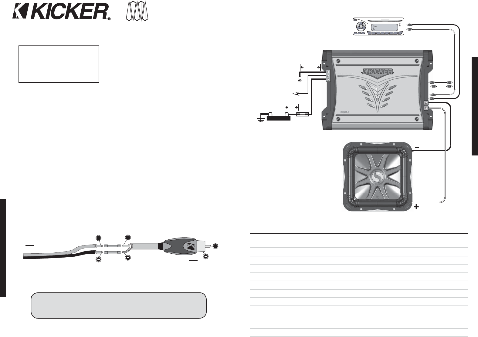
3. Confi guration The following diagram shows the most common confi gurations for your Kicker ZX
series amplifi er.
One Channel Operation These ZX amplifi ers are capable of operating into a minimum impedance of
2 ohms. If you are using multiple voice coils, the net impedance of the voice coils must be equal to or
greater than 2 ohms.
ZX.1SeriesAmplifi er
Owner’sManual
MonoChannel: ZX400.1 / ZX500.1 / ZX750.1
Authorized Kicker Dealer:
Purchase Date:
Amplifi er Model Number:
Amplifi er Serial Number:
Congratulations on your
KICKER purchase!
Please record your purchase
information and keep your sales
receipt for validation of warranty.
__________________________
__________________________
__________________________
__________________________
INSTALLATION
2
ZX.1AMPLIFIER
CONFIGURATION
3
+12V
18"
(45cm)
24"
(60cm)
KUNEK
10 - COMA
Figure 2
Minimum impedance of 2 ohms while in bridged operation
Ground
Remote
Turn-On
Fuse
Battery
One Channel Operation (Mono)
Note: To get the best performance from your new Kicker Amplifi er, we recommend using genuine Kicker Accessories and Wiring.
+
+
>
+
>
Core Cable
Ground or Shielding
High-level Speaker Output Wire
To Amplifi er
To Source Unit
Figure 1
ModelZX400.1 1 (ONE) 40 AMPERE FUSE PowerGroundWire 4GA
ModelZX500.1 1 (ONE) 60 AMPERE FUSE PowerGroundWire 4GA
ModelZX750.1 1 (ONE) 80 AMPERE FUSE PowerGroundWire 4GA
Signal In
Signal Out
Source Unit
Performance
Model ZX400.1 ZX500.1 ZX750.1
RMS Power in Watts, all channels driven @14.4
Volts, 4Ω mono, ≤ 1% THD+N
200 x 1 250 x 1 375 x 1
@ 2Ω mono, ≤ 1% THD+N 400 x 1 500 x 1 750 x 1
Length: in(cm) 10 1/4 (26) 12 (30.5) 14 11/16 (37.3)
Specifi cations common to all models:
Height: in(mm) 2 1/8 (54mm)
Width: in(mm) 9 5/8 (244mm)
Frequency Response, ± 1 db: 25 Hz - 200 Hz
Signal-to-Noise Ratio: >95db, a-weighted, re: rated power
Input Sensitivity:
Low Level: 125mV-5V
High Level: 250mV-10V
Variable Electronic Crossover: Variable Low-Pass, 50 - 200Hz, 24dB per octave
Subsonic Filter: 24 db/Octave Subsonic Filter Fixed @ 25Hz
Bass Boost: Variable 0-18db Bass Boost @ 40Hz