


WiringOptions
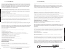
Solo-Baric subwoofers are available with dual 2Ω (ohm) or dual 4Ω voice coils. Both coils must be
connected to a source of amplification. The dual 2Ω woofer will generate a 1Ω load if the coils are
wired in parallel or a 4Ω load in series. The dual 4Ω woofer will provide a 2Ω load wired in parallel or
8Ω load wired in series. The terminals with the white dots are for the first voice coil. The terminals with
solid-red and solid-black markings are for the second voice coil. See Figures 1 and 2.
CONFIGURATION
SOLO-BARICL7SUBWOOFER
S15L7 /S12L7 /S10L7 /S8L7
Models:
Solo-BaricL7Subwoofer
Owner’sManual
Congratulations on your
KICKER purchase
Please record your purchase
information and keep your sales
receipt for validation of warranty.
Authorized Kicker Dealer:
Purchase Date:
Subwoofer Model Number:
Subwoofer Serial Number:
_________________________
_________________________
_________________________
_________________________
Please allow two weeks of break-in time for the subwoofer to reach optimum bass performance.
2 3
INSTALLATION
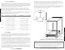
CutoutDimensions
SealedEnclosureApplications
The Solo-Baric generates more sound pressure than an equivalently-sized round speaker and excels
when used in the recommended sealed boxes. These sealed enclosure designs give the smoothest
response with increased energy at the lowest frequencies, 20 to 30Hz. These designs deliver massive
amounts of highly-accurate bass and can be driven with punishing levels of amplifier power.
The Solo-Baric high performance suspension system can operate in a larger sealed enclosure. This
maximum enclosure volume application is ideal for SQ (ultra sound quality) installations. The SQ
enclosure generates a very flat response curve and superbly extends the subbass response.
Solo-Baric woofers perform well in any size sealed enclosure between the Compact and SQ volume
recommendations. These systems will exhibit benefits of both designs: Compact produces high-impact
bass, and SQ generates low bass frequency protraction. Overall, the system will sound more like the
recommended enclosure design it is closest to in enclosure volume. These enclosure recommendations
have been calculated with the airspace inside the enclosure and include the displacement of the woofer.
All sealed-enclosure airspace should be filled to 50% loose poly-fil (polyester fiberfill) stuffing. Do not
make the airspace greater than the SQ, maximum enclosure volume, recommendation.
Model:
S8L7
S10L7
S12L7
S15L7
SealedSQ (MaximumEnclosureVolume)
.75 ft
3
(21.24L) Power Handling = 200W RMS
1.0 ft
3
(28.32L) Power Handling = 600W RMS
2.0 ft
3
(56.64L) Power Handling = 750W RMS
6.0 ft
3
(169.9L) Power Handling = 1000W RMS
SealedCompact (MinimumEnclosureVolume)
.33 ft
3
(9.34L) Power Handling = 200W RMS
.66 ft
3
(18.69L) Power Handling = 600W RMS
.88 ft
3
(24.92L) Power Handling = 750W RMS
1.5 ft
3
(42.48L) Power Handling = 1000W RMS
Model:
Nominal Impedance [Zn], ohm [per coil]
Resonance Frequency [fs], Hz
Power Handling Watts, Peak (RMS)
Total Q-Factor [Qts]
Equivalent Volume [Vas], ft
3
(L)
Outer Frame Dimension, in (cm)
Mounting Depth, in (cm)
S12L7
2 or 4
34.0
1500 (750)
.513
2.2 (62.5)
12 5/8 (32)
6 13/16 (17.3)
S10L7
2 or 4
37.5
1200 (600)
.584
.97 (27.5)
10 11/16 (27.1)
6 1/4 (15.9)
S8L7
2 or 4
47.2
900 (450)
.644
.36 (10.3)
8 13/16 (22.4)
4 3/4 (12.1)
S15L7
2 or 4
26.3
2000 (1000)
.507
5.2 (148.6)
15 5/8 (39.7)
8 11/16 (22.1)
Measurements based on the 4 ohm dual voice coil models.
Performance
Model:
S8L7
S10L7
S12L7
S15L7
Panel B, in (cm)
10x8 (25.4x20.3)
12x10.5 (30.5x26.7)
13x11.5 (33x29.2)
16.5x11.5 (42x29.2)
Panel A, in (cm)
10x10 (25.4x25.4)
12x12 (30.5x30.5)
13x13 (33x33)
16.5x16.5 (42x42)
Volume, ft
3
(L)
.33 (9.34)
.66 (18.69)
.88 (24.92)
1.50 (42.48)
Panel C, in (cm)
8x8.5 (20.3x21.6)
10.5x10.5 (26.7x26.7)
11.5x11.5 (29.2x29.2)
15x11.5 (38.1x29.2)
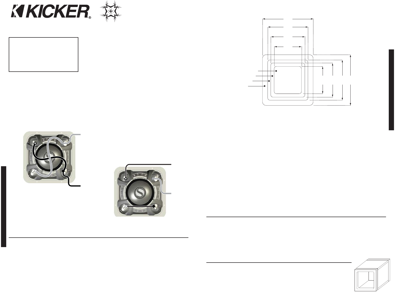
Panel Dimensions for CompactSealedEnclosures using 3/4” (1.9cm) thick MDF:
ParallelWiring
SeriesWiring
Dual 2Ω Voice Coils = 4Ω Load
Dual 4Ω Voice Coils = 8Ω Load
Dual 2Ω Voice Coils = 1Ω Load
Dual 4Ω Voice Coils = 2Ω Load
Figure 1
Figure 2
Coil 2 +
Coil 2 +
Coil 1 +
Coil 1 +
Coil 1 -
Coil 1 -
Coil 2 -
Coil 2 -
Amplifier -
Speaker
Connection
Amplifier -
Speaker
Connection
Amplifier +
Speaker
Connection
Amplifier +
Speaker
Connection
Figure 3
13 3/4”
(34.9cm)
11 1/16”
(28.1cm)
9 5/16”
(23.7cm)
7 1/4”
(18.4cm)
7 1/4”
9 5/16”
11 1/16”
13 3/4”
S8L7
S10L7
S12L7
S15L7
S8L7 - 1.5” (38.1mm)
S10L7 - 1.5” (38.1mm)
S12L7 - 1.75” (44.5mm)
S15L7 - 1.7” (43.2mm)
CornerRadius:
A
B
C
Figure 4