


4 5
INSTALLATION
SOLOXSUBWOOFERSPAIRASSEMBLY
INSTALLATION
Locator Hole
Locator Pin
New SPAIR
Connect
Speaker
Cable
Wires
New SPAIR
BAM
Remove
Gap Cap
Locator Hole
Locator Pin
New SPAIR
BAM
1
2
3
4
5
6
7
8
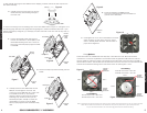
Fit the new SPAIR to the BAM with the
10-24 Acorn Head Bolts. We have enclosed four
(4) extra Acorn Head Bolts.
Hand tighten the 10-24 Acorn Head Bolts in the order
shown in Figure 10. Then use a wrench or socket
driver to securely fasten the bolts. This will ensure a
proper fit and alignment.
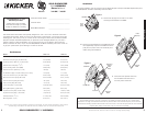
Connect the speaker cable wires (used to
connect the subwoofer to the amplifier) to the
new SPAIR’s Binding Posts. The Locator Pin
and Locator Hole will properly align the SPAIR
to the BAM.
Remove the Gap Cap before inserting the new
SPAIR.
Carefully insert the new SPAIR back into the
BAM; do not damage the voice coil. The
Locator Pin on the BAM and the Locator Hole
in the SPAIR must line up. The ARCTIC
(Aluminum Rapid Cooling Thermal Induction
Centering) Cap, located on the top of the
extended pole piece, will help to center the
new SPAIR as you lower it into the BAM.
When properly aligned these assemblies easily
slide.
WiringOptions
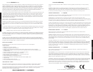
SoloX subwoofers are available with dual 4Ω (ohm) or dual 2Ω voice coils. Both coils must be
connected to a source of amplification. The dual 4Ω woofer will generate a 2Ω load if the coils are
wired in parallel or a 8Ω load in series. The dual 2Ω woofer will provide a 1Ω load wired in parallel or
4Ω load wired in series. The terminals with the white dots are for the first voice coil. The terminals with
solid-red and solid-black markings are for the second voice coil. See Figures 1 and 2.
ParallelWiring
Dual 4Ω Voice Coils = 2Ω Load
Dual 2Ω Voice Coils = 1Ω Load
Figure 11
Coil 1 +
Coil 2 +
Coil 2 -Coil 1 -
Amplifier -
Speaker
Connection
Amplifier
+
Speaker
Connection
SeriesWiring
Dual 4Ω Voice Coils = 8Ω Load
Dual 2Ω Voice Coils = 4Ω Load
Figure 12
Coil 1 +
Coil 2 +
Coil 2 -Coil 1 -
Amplifier -
Speaker
Connection
Amplifier
+
Speaker
Connection
3. Connect the wiring to the four binding posts on the new SPAIR. Refer to Figure 11 and Figure 12 on
the following page and follow the appropriate wiring diagram to achieve the desired ohm load. If your
system was properly configured, you will simply reconnect the wires to the voice coils as they were on
the old SPAIR.
a.
b.
c.
d.
e.
Figure 6
Figure 7
Figure 8
Figure 9
Figure 10
Note: All specifications and performance figures are subject to change. Please visit the www.kicker.com for the most current information.
Please allow two weeks of break-in time for the subwoofer to reach optimum performance. To get the best performance
from your new Kicker subwoofers, we recommend using genuine Kicker Accessories and Wiring.
2. After carefully removing the new SPAIR from the shipping container, remove the Coil Cap from the
new SPAIR assembly.
Carefully remove the Coil Cap from the new
SPAIR assembly while avoiding damage to
the voice coils.
a.
Coil Cap
New SPAIR
Figure 4
Enclosure
Baffle
Enclosure
Baffle
Enclosure
Baffle
Enclosure
Baffle
BAM
BAM