


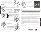
Fit the SPAIR to the BAM with the
10-24 Acorn Head Bolts. We have
enclosed four (4) extra Acorn Head
Bolts. See Figure 18.
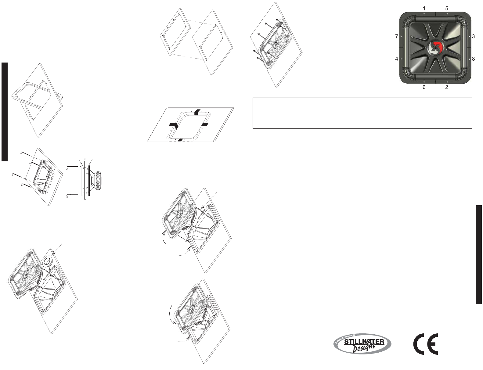
Hand tighten the 10-24 Acorn Head
Bolts in the order shown in Figure 19.
Then use a wrench or socket driver to
securely fasten the bolts. This will
ensure a proper fit and alignment.
InternationalWarranty
Contact your International Kicker dealer or distributor concerning specific procedures for your country's warranty
policies.
WARNING: KICKER products are capable of producing sound levels that can permanently damage your hearing!
Turning up a system to a level that has audible distortion is more damaging to your ears than listening to an
undistorted system at the same volume level. The threshold of pain is always an indicator that the sound level is too
loud and may permanently damage your hearing. Please use common sense when controlling volume.
GARANTÍA INTERNACIONAL VersiónEspañol
Comuníquese con su concesionario o distribuidor Kicker internacional para obtener infor ación sobre procedimientos
específicos relacionados con las normas de garantía de su país.
ADVERTENCIA: Los excitadores Kicker son capaces de producir niveles de sonido que pueden dañar
permanentemente el oído. Subir el volumen del sistema hasta un nivel que produzca distorsión es más dañino para el
oído que escuchar un sistema sin distorsión al mismo volumen. El dolor es siempre una indicación de que el sonido es
muy fuerte y que puede dañar permanentemente el oído. Sea precavido cuando controle el volumen.
INTERNATIONALE GARANTIE DeutscheVersion
Nehmen Sie mit Ihren internationalen Kicker-Fachhändler oder Vertrieb Kontakt auf, um Details über die
Garantieleistungen in Ihrem Land zu erfahren.
WARNUNG: KICKER-Treiber können einen Schallpegel erzeugen, der zu permanenten Gehörschäden führen kann!
Wenn Sie ein System auf einen Pegel stellen, der hörbare Verzerrungen erzeugt, schadet das Ihren Ohren mehr, als ein
nicht verzerrtes System auf dem gleichen Lautstärkepegel. Die Schmerzschwelle ist immer eine Anzeige dafür, dass
der Schallpegel zu laut ist und zu permanenten Gehörschäden führen kann. Seien Sie bei der Lautstärkeeinstellung
bitte vernünftig!
GARANTIE INTERNATIONALE VersionFrançaise
Pour connaître les procédures propres à la politique de garantie de votre pays, contactez votre revendeur ou
distributeur International Kicker.
AVERTISSEMENT: Les haut-parleurs Kicker ont la capacité de produire des niveaux sonores pouvant endommager
l'ouïe de façon irréversible ! L'augmentation du volume d'un système jusqu'à un niveau présentant une distorsion
audible endommage davantage l'ouïe que l'écoute d'un système sans distorsion au même volume. Le seuil de la
douleur est toujours le signe que le niveau sonore est trop élevé et risque d'endommager l'ouïe de façon irréversible.
Réglez le volume en faisant prevue de bon sens !
SOLOXSUBWOOFER
6 7
GARANTIE
WARRANTY
03062007+07SOLOX
P.O. Box 459 • Stillwater, Oklahoma 74076 • U.S.A. • (405) 624-8510
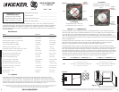
A Note on PowerHandlingCapacity SoloX subwoofers will handle massive amounts of power in any of the
recommended enclosures, minimum or maximum. The smaller enclosures are best for use in limited-space
applications. The larger recommended enclosures will yield more bass at the resonate frequency of the enclosure.
The listed Power Handling capacities assume that both voice coils are in use with the appropriate sub-sonic/resonate
frequency filter. Always connect both coils in a dual voice-coil speaker.
RemovalMountingAssembly (Continued)
Please follow these instruction to insure proper installation.
Use a jigsaw or router to cut the woofer cutout. Use a 5/16 or
11/32” (8 - 8.8mm) drill bit for the mounting holes. See Figure 11.
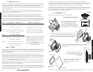
Note: The following steps require the assistance of
another person.
Insert the SPLAT into the cutout (inside the enclosure) and move it into
position. See Figure 12.
Use masking tape to temporarily
hold the SPLAT in place inside
the enclosure. This will be
necessary for securing the BAM.
This tape can be removed after
the corner fastening
hardware has been installed.
See Figure 13.
With the help of an assistant, insert the BAM and start
fastening the corner hardware. Remove the masking tape.
Tighten the Phillips Head Machine Screws to secure the
BAM to the enclosure
baffle. See Figure 14.
Pull the speaker cable wires (used to connect the subwoofer to the
amplifier) through the BAM and connect them to the SPAIR’s
Binding Posts. The Locator Pin and Locator Hole will properly align
the SPAIR to the BAM.
See Figure 15.
Remove the Gap Cap before
inserting the SPAIR.
See Figure 16.
Carefully insert the SPAIR back into
the BAM; do not damage the voice
coil. The Locator Pin on the BAM and
the Locator Hole in the SPAIR must
line up. The ARCTIC (Aluminum Rapid
Cooling Thermal Induction Centering)
Cap, located on the top of the extended pole piece of the SPAIR, will
help to center the SPAIR as you lower it into the BAM. When properly
aligned these assemblies easily slide together. See Figure 17.
Figure 11
Figure 12
Wood Template
Enclosure Baffle
Enclosure
Baffle
SPLAT
Inside the
Enclosure
Figure 13
Enclosure Baffle
SPLAT
Inside the
Enclosure
Masking
Tape
Figure 14
BAM
Enclosure Baffle
SPLAT
Enclosure
Baffle
Machine
Screws
10-24
Figure 15
Figure 16
Figure 17
Locator Hole
Locator Pin
SPAIR
Connect
Speaker
Cable
Wires
Enclosure
Baffle
SPAIR
BAM
BAM
Remove
Gap Cap
Enclosure
Baffle
Locator
Hole
Locator Pin
SPAIR
Enclosure
Baffle
BAM
Figure 18
1
2
3
4
5
6
7
8
Figure 19