


2
IX AMPLIFIERS
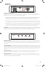
IX.2-SERIES AMPLIFIERS Owner’s Manual
IX500.2
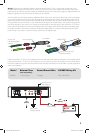
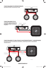
INSTALLATION
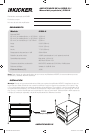
Mounting: Choose a structurally sound location to mount your KICKER amplifi er. Make sure there are no items
behind the area where the screws will be driven. Choose a location that allows at least 4” (10cm) of open
ventilation for the amplifi er. If possible, mount the amplifi er in the climate-controlled passenger compartment. Drill
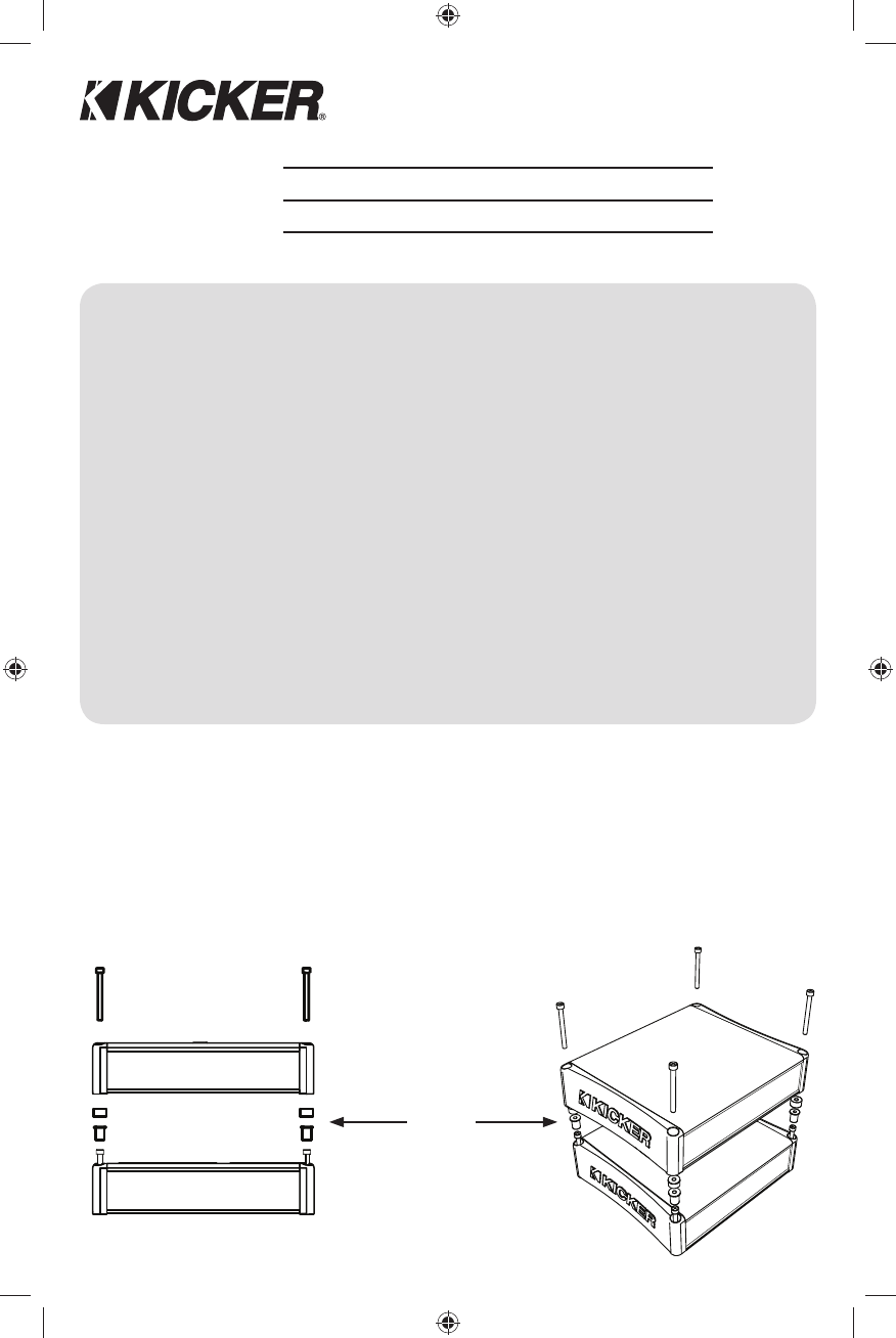
four holes using a 7/64” (3mm) bit and use the supplied #8 screws to mount the amplifi er. Use the IXSM or IXSK
mounting kits (sold separately) to stack multiple IX amplifi ers.
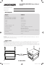
PERFORMANCE
Authorized KICKER Dealer:
Purchase Date:
Serial Number:
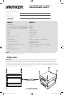
Model: IX500.2
RMS Power
@ 14.4V, 4Ω stereo, 1% THD+N
@ 14.4V, 2Ω stereo, 1% THD+N
@ 14.4V, 4Ω mono, 1% THD+N
125W x 2
250W x 2
500W x 1
Length 9-3/8” (238mm)
Height 2-3/16” (55mm)
Width 7-7/8” (200mm)
Frequency Response ± 1dB 20Hz–20kHz
Signal-to-noise Ratio >95dB, A-weighted, re: rated power
Input Sensitivity Low Level: 125mV–5V
High Level: 250mV–10V
Electronic Crossover Selectable HI/LO/OFF, Variable 50–200Hz, 12dB/octave
Bass Boost Variable 0–18dB @ 40Hz
Maximum Effi ciency (2Ω) >80%
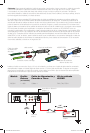
Pro Tip: To get the best performance from your new KICKER Amplifi er and extend the warranty by 1 year, use
genuine KICKER accessories and wiring.
IXSK
sold separately
2010 IX 500.2 RevF.indd 22010 IX 500.2 RevF.indd 2 11/5/2010 12:32:10 PM11/5/2010 12:32:10 PM