


2
COMPVX SUBWOOFER
3
The Kicker CompVX subwoofers were specially designed for “Livin’ Loud” out in the harsh automotive
environment. CompVX subwoofers are extremely versatile and surpass the competition in a sealed or
vented box. They are made of advanced materials and construction techniques to maintain optimal
performance for years to come.
SPECIFICATIONS
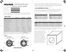
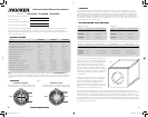
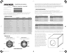
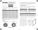
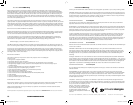
WIRING
CompVX subwoofers are available with dual 2 (ohm) or dual 4 voice coils. Both coils must be
connected to a source of amplifi cation. The dual 2 woofer will generate a 1 load if the coils are wired
in parallel or a 4 load in series. The dual 4 woofer will provide a 2 load wired in parallel or 8 load
wired in series. The terminals with the white dots are for the fi rst voice coil. The terminals with solid-red
and solid-black markings are for the second voice coil. See Figure 1.
SEALED ENCLOSURE APPLICATIONS
The CompVX generates more sound pressure than competing subwoofers on the market and excels
when used in the recommended sealed boxes. These sealed enclosure designs give the smoothest
response with increased energy at the lowest frequencies, 20 to 30Hz. These designs deliver massive
amounts of highly-accurate bass and can be driven with punishing levels of amplifi er power.
The CompVX high performance suspension system can operate in a larger sealed enclosure. This
maximum enclosure volume application is ideal for SQ (ultra sound quality) installations. The SQ enclosure
generates a very fl at response curve and superbly extends the subbass response.
CompVX woofers perform well in any size
sealed enclosure between the Compact
and SQ volume recommendations. These
systems will exhibit benefi ts of both designs:
Compact produces high-impact bass,
and SQ generates low bass frequency
protraction. Overall, the system will sound
more like the recommended enclosure
design it is closest to in enclosure volume.
These enclosure recommendations have
been calculated with the airspace inside the
enclosure and include the displacement of
the woofer. All sealed-enclosure airspace
should be fi lled to 50% loose poly-fi l
(polyester fi berfi ll) stuffi ng. Do not make the
airspace greater than the SQ, maximum
enclosure volume, recommendation.
CompVX Subwoofer Owner’s Manual
Authorized KICKER Dealer:
Purchase Date:
Speaker Model Number:
Speaker Serial Number:
Model CompVX10 CompVX12 CompVX15
Nominal Impedance [Zn], ohm 2 or 4 2 or 4 2 or 4
Resonance Frequency [fs], Hz 35.4 28.5 23.7
Power Handling Watts, Peak (RMS) 1200 (600) 1500 (750) 2000 (1000)
Sensitivity [SPLo], dB @ 1W, 1m 85.7 87.1 91.6
Effective Excursion [EXmax™], in (mm) .61 (15.4) .61 (15.4) .69 (17.4)
DC Resistance [Re], ohm 3.40 3.70 4.2
Mechanical Q-Factor [Qms] 10.754 10.098 7.521
Electrical Q-Factor [Qes] .419 .396 .222
Total Q-Factor [Qts] .403 .381 .216
Equivalent Volume [Vas], ft³ (L) .811 (22.99) 2.04 (57.82) 5.5 (156.71)
Net Displacement, in³ (cc) 92.7 (1519) 105 (1720.6) 179 (2933.3)
Outer Frame Diameter, in (cm) 10-11/16 (27.1) 12-9/16 (31.8) 15-7/16 (39.2)
Hole Cut-Out Diameter, in (cm) 9-3/16 (23.3) 11-1/16 (28) 13-13/16 (35)
Mounting Depth, in (cm) 5-15/16 (15.1) 6-11/16 (16.9) 8-1/2 (21.5)
Model Volume ft
3
(L) Panel A in. (cm) Panel B in. (cm) Panel C in. (cm)
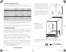
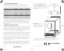
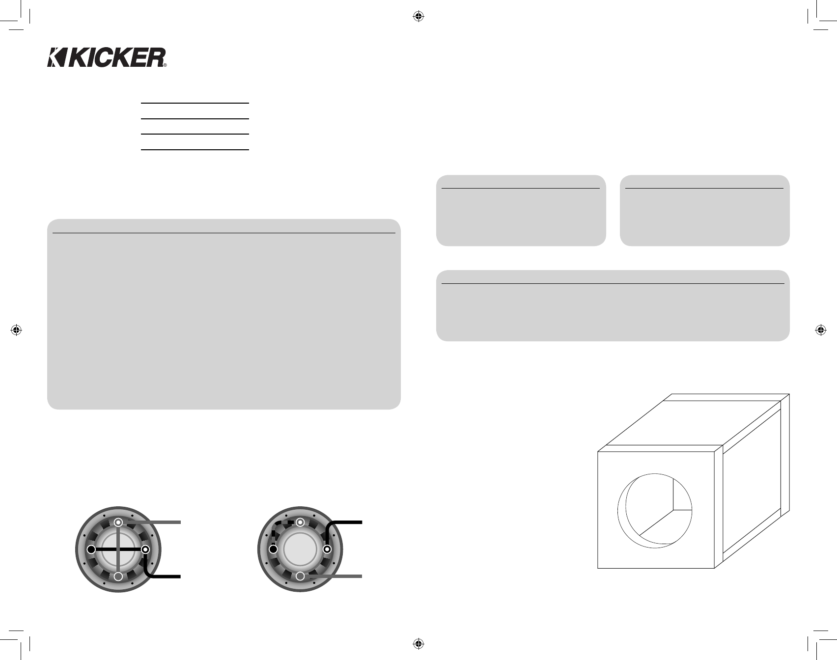
CompVX10 .8 (22.7) 13.5x13.5 (34.3x34.3) 13.5X10.125 (34.3X25.7) 12X10.125 (30.5X25.7)
CompVX12 1 (28.32) 14.5x14.5 (36.8x36.8) 14.5X11 (36.8X27.9) 13X11 (33X27.9)
CompVX15 1.8 (51) 17.25x17.25 (43.8x43.8) 17.25X13.5 (43.8X34.3) 15.75X13.5 (40X34.3)
Model Volume ft
3
(L) Power Handling
CompVX10 .8 (22.7) 600W RMS
CompVX12 1 (28.3) 750W RMS
CompVX15 1.8 (51) 1000W RMS
Model Volume ft
3
(L) Power Handling
CompVX10 3 (85) 300W RMS
CompVX12 4.6 (130) 300W RMS
CompVX15 5.2 (147) 500W RMS
CompVX10 / CompVX12 / CompVX15
Models:
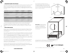
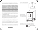
Panel Dimensions for Compact Sealed Enclosures using 3/4” (1.9cm) thick MDF (See Figure 2)
Sealed Compact
Sealed SQ
Note: All specifi cations and performance fi gures are subject to change. Please visit www.kicker.com for the most
current information. To get the best performance from your new KICKER Subwoofer, we recommend using genuine
KICKER Accessories and Wiring. Please allow two weeks of break-in time for the subwoofer to reach optimum
performance.
A
B
C
Figure 2
Figure 1
Series WiringParallel Wiring
Dual 2 Voice Coils = 4 Load
Dual 4 Voice Coils = 8 Load
Dual 2 Voice Coils = 1 Load
Dual 4 Voice Coils = 2 Load
Coil 1+
Coil 1+
Coil 2+
Coil 2+
Coil 2-
Coil 2-
Coil 1-
Coil 1-
2010 CompVX e01.indd 2-32010 CompVX e01.indd 2-3 10/21/2009 3:34:01 PM10/21/2009 3:34:01 PM