


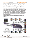

inputs is for receiving the Source or input signal; the
other input is used for the “Loop-Through” signal, for
passing the signal to the next amplifier in the chain
of series. Either input can be used as the “Source”
input or as the “Loop-Through” input (to send the sig-
nal to the next KD-CDA12 or KD-DA6.) The Mode 2
setting is used for all KD_CDA12 in the chain except
for the last unit which must be set to Mode 3 (See
below for appropriate dip switch setting). A maxi-
mum of 4 KD-CDA12’s can be connected in a “Daisy
Chain” using this hook-up method.
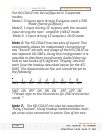
The dipswitches on the unit should be set to the fol-
lowing:
_1 2 3 4 _5 _6 7 8
SW1 OFF ON OFF OFF ON ON OFF OFF
_________________________________________________________________________________________________
_
SW2 OFF ON OFF OFF OFF ON OFF OFF
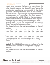
* Please refer to the illustration for NX12 Daisy
Chain.*
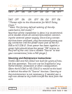
Mode3: The KD-CDA12 can can be configured to dis-
tribute 1 input “Source” to 12 different “Display”
devices.
The dipswitches on the unit should be set to the fol-
lowing:
Page 8
HD View 6
OPERATING INSTRUCTIONS
Model KD-DA6