


8
Preparations
KRF-V7010/V6010/V5010 (En/T)
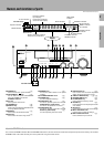
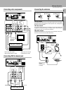
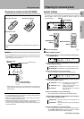
REC OUT
PHONO CD MD / TAPE VIDEO 2 / MONITOR
PLAY IN REC OUT PLAY IN
L
R
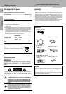
Make connections as shown below.
When connecting the related system components, be sure
to also refer to the instruction manuals supplied with the
components you are connecting.
Do not connect the power cord to a wall outlet until all
connections are completed.
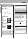
Microcomputer malfunction
If operation is not possible or an erroneous display appears, even
though all connections have been made properly, reset the micro-
computer referring to “In case of difficulty”. ∞
Notes
1. Connect all cords firmly. Loose connections may prevent proper
sound transmission or produce noise.
2. Be sure to remove the power cord from the AC outlet before plugging
or unplugging any connection cords. Plugging / unplugging connec-
tion cords without disconnecting the power cord can cause malfunc-
tions and may damage the unit.
3. Do not connect power cords from components whose power con-
sumption is larger than what is indicated on the AC outlet at the rear
of this unit.
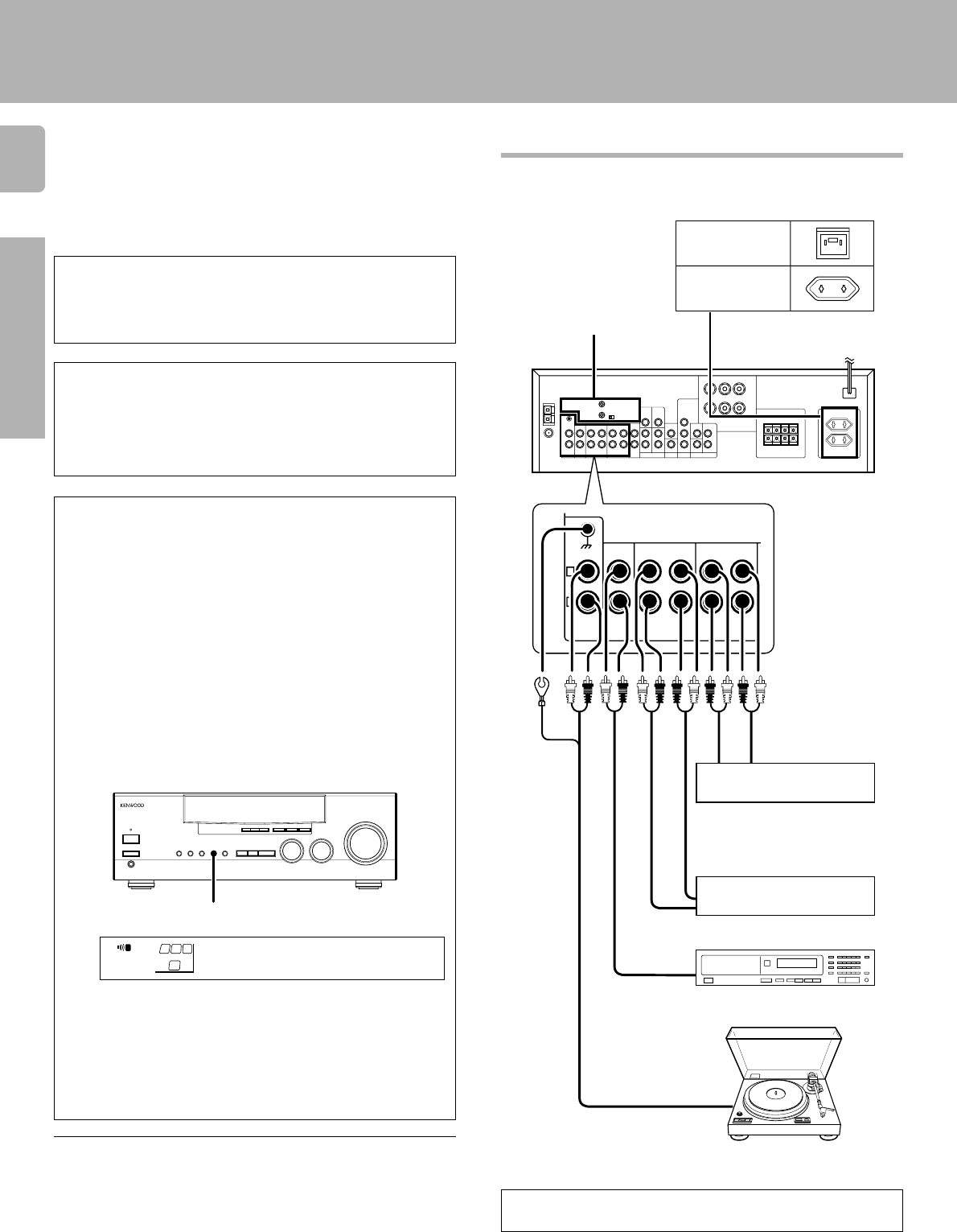
Connecting audio components
Caution regarding placement
To AC wall outlet
Cassette deck or
MD recorder
CD player
IN
OUT
Record player
SYSTEM CONTROL
jacks 0
Shape of AC outlets
For U.K.
For other countries
Cassette deck or
graphic equalizer ^
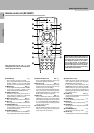
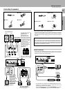
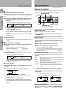
Setting up the system
To maintain proper ventilation, be sure to leave a space around the
unit (from the largest outer dimensions, including projections) equal
to, or greater than shown below:
Left and right panels: 10 cm, Rear panel: 10 cm, Top panel: 50 cm
IN
OUT
OUT
OUT
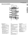
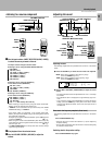
VIDEO 2/MONITOR jacks
The receiver’s VIDEO 2/MONITOR jacks can be used in two different
ways. Make the appropriate setting for the component connected to
the jack when the receiver is turned on.
Use as a VIDEO 2 jack
You can connect a video deck or the like to these jacks and perform
video playback and recording. The initial factory setting is “VIDEO
2”.
Use as a MONITOR jack
You can connect a cassette deck or the like to these jacks and make
use of the deck’s monitoring function during recording. Alternately,
you can connect a graphic equalizer to these jacks to apply compen-
sation to the music signal.
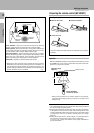
To use the VIDEO 2/MONITOR jacks as MONITOR jacks, hold down
the VIDEO 2/MONITOR key of the main unit for more two seconds so
that the indication shown below appears.
• At the same time the setting is switched to “MONITOR,” the audio
input source switches to tuner and the video input source switches
to VIDEO 1.
• To switch the setting back to “VIDEO 2,” once again hold down the
VIDEO 2/MONITOR key for two seconds or more.
• If you decide to use the VIDEO 2/MONITOR jacks as MONITOR
jacks, make sure to delete the “VIDEO 2 (VCR2)” input from the
preset remote control (RC-R0507). RC6
VIDEO 2/MONITOR
M
ONIT RO
FM
AM
kHz
MHz
STEREO
DSP
S.DIRECT
A
SP
MUTE
DOWNMIX
PRO LOGIC
TUNED
MEMO.
AUTO
ST.
AUTO SOUND
SW
R
L
DIGITAL
B
MONITOR
To use these jacks as MONITOR
jacks, you must change the
appropriate setting.
To use the receiver for video recording, connect a video deck to
the VIDEO 2/MONITOR jacks.