


— 14 —
English
Installation
■
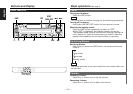
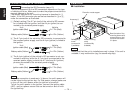
InstallationConnecting Cables to Terminals
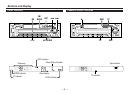
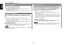
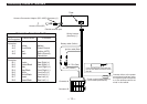
Connecting the ISO Connector (see p.13)
The pin arrangement for the ISO connectors depends on the type
of vehicle you drive. Make sure to make the proper connections to
prevent damage to the unit.
The default connection for the wiring harness is described in
1
below. If the ISO connector pins are set as described in 2 or 3,
make the connection as illustrated.
2WARNING
Unit Vehicle
Ignition cable (Red)
Battery cable (Yellow)
A–7 Pin (Red)
A–4 Pin (Yellow)
Unit Vehicle
Ignition cable (Red)
Battery cable (Yellow)
A–7 Pin (Red)
A–4 Pin (Yellow)
Unit Vehicle
Ignition cable (Red)
Battery cable (Yellow)
A–7 Pin (Red)
A–4 Pin (Yellow)
When the connection is made as in
3 above, the unit's power will
not be linked to the ignition key. For that reason, always make sure
to turn off the unit's power when the ignition is turned off.
To link the unit's power to the ignition, connect the ignition cable
(ACC...red) to a power source that can be turned on and off with
the ignition key.
NOTE
1 (Default setting) The A-7 pin (red) of the vehicle's ISO connec-
tor is linked with the ignition, and the A-4 pin (yellow) is con-
nected to the constant power supply.
2 The A-7 pin (red) of the vehicle's ISO connector is connected to
the constant power supply, and the A-4 pin (yellow) is linked to
the ignition.
3 The A-4 pin (yellow) of the vehicle's ISO connector is not con-
nected to anything, while the A-7 pin (red) is connected to the
constant power supply (or both the A-7 (red) and A-4 (yellow)
pins are connected to the constant power supply).
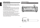
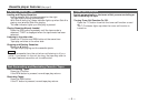
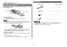
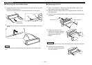
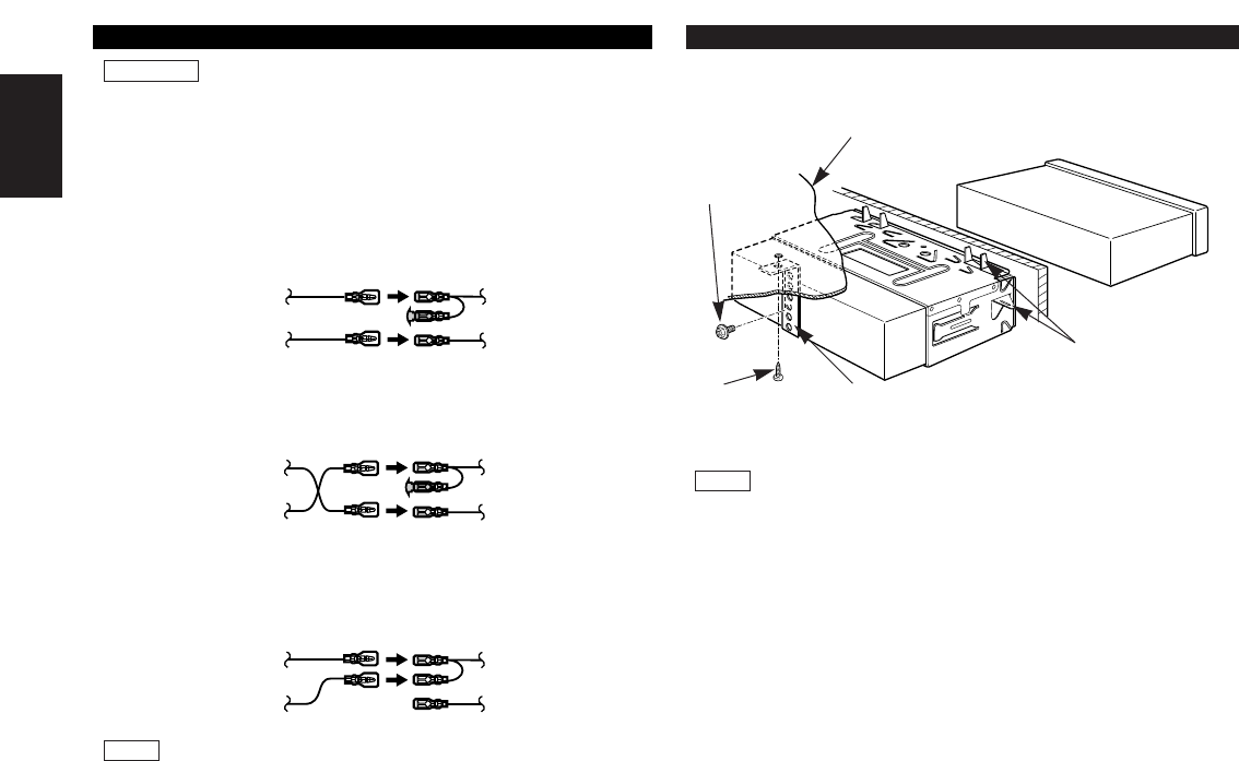
Make sure that the unit is installed securely in place. If the unit is
unstable, it may malfunction (eg, the sound may skip).
NOTE
Bend the tabs of the
mounting sleeve with
a screwdriver or simi-
lar utensil and attach
it in place.
Metal mounting
strap
(commercially
available)
Self-tapping
screw
(commercial-
ly available)
Firewall or metal support
Accessory3