


9
Preparations
OperationsOther
KR-V9090/8090 (En/T)
TAPE/MDCDPHONO
PLAY
IN
REC
OUT
SIGNAL
GND
L
R
VIDEO1 VIDEO3VIDEO2
PLAY
IN
PLAY
IN
PLAY
IN
REC
OUT
ADAPTOR
INOUT
AUDIO
SUB
WOOFER
SURROUND
FRONT
CENTER
L
R
AUX.6CH.INPUT
ƒ
SYSTEM CONTROL
SL 16 XS 8
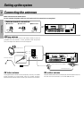
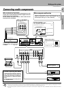
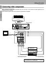
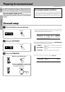
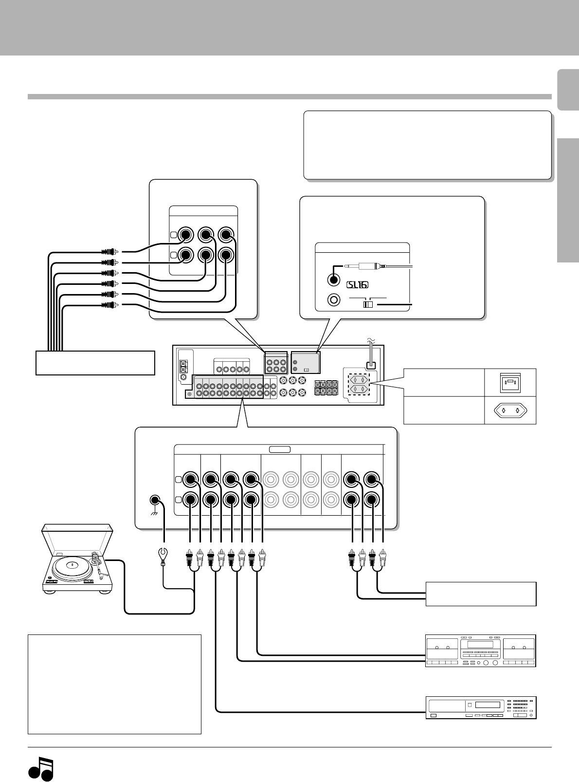
Make connections as shown below.
When connecting the related system components, be sure
to also refer to the instruction manuals supplied with the
components you are connecting.
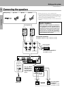
Do not connect the power cord to a wall outlet until all
connections are completed.
Microcomputer malfunction
If operation is not possible or an erroneous display appears, even
though all connections have been made properly, reset the
microcomputer referring to “In case of difficulty”. T
1. Connect all cords firmly. Loose connections may prevent proper sound transmission or produce noise.
2. Be sure to remove the power cord from the AC outlet before plugging or unplugging any connection cords. Plugging / unplugging connection
cords without disconnecting the power cord can cause malfunctions and may damage the unit.
3. Do not connect power cords from components whose power consumption is larger than what is indicated on the AC outlet at the rear of
this unit.
Connecting audio components
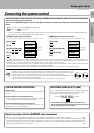
Setting up the system
Notes
Notes
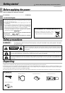
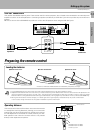
Caution regarding placement
To maintain proper ventilation, be sure to
leave a space around the unit (from the
largest outer dimensions, including pro-
jections) equal to, or greater than shown
below:
Left and right panels: 10 cm, Rear panel: 10
cm, Top panel: 50 cm
SYSTEM CONTROL
cord
SYSTEM CONTROL
switch
To AC wall outlet
Cassette deck or
MD recorder
CD player
REC
PLAY
IN
OUT
6CH input (M.INPUT)
(KR-V9090 only)
Record player
Multi-channel decoder
(etc.)
SYSTEM CONTROL jacks
For SYSTEM CONTROL connections to
KENWOOD components !
(KR-V9090 only)
The sound input to AUX.6CH.INPUT
is paired with the video signal input
to VIDEO 2. 0¡
Shape of AC outlets
U.K.
Except for U.K.
Graphic equalizer
¡