


2-English
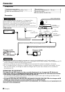
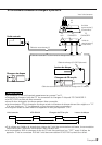
Connection
CHANGER 2
TO
CHANGER 1CHANGER 1
TO
CONTROLLER
TO
H/U
TO
SWITCH
AUX
OFF ON
SWITCH
PROTOCOL
ON
IN
AUX
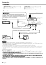
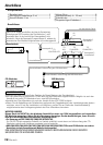
Connection cable3
Centre unit
Connection cable (supplied with the CD changer)
Connection cable (supplied with the MD changer)
CD changer
MD Changer
Switching unit1
(Front side)
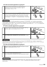
If you connect a model which can switch between disc
changers 1 and 2 by the centre unit (Unit group B/C/D), the
controller2 must not be connected. If it is connected, the
disc changers may not work properly.
2
CAUTION
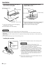
• After connecting the equipment, press the reset button on the centre unit.
• The figure shows that one CD changer and one MD changer are connected. Two CD changers or two
MD changers may be connected.
•A disc player such as the KDC-D300 may be connected instead of the disc changer.
• If you wish to adjust the cable length in accordance with the installation location of the switching unit,
such as in the trunk space, the disc changer extension cable may be used instead of the connection
cable3.
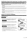
IMPORTANT INFORMATION
This unit is NOT designed to be connected directly to a CD changer that was manufactured and
sold before 1994. If you plan to use such units, please read the following information carefully.
• To control KDC-C600/ KDC-C800/ KDC-601/ KDC-401
A CA-DS100 (sold separately as an optional accessory), along with the extension cord supplied with the
CD changer, are required.
• KDC-C200/ KDC-C300/ KDC-C301/ KDC-C400/ KDC-C100/ KDC-C302/ C205/ C705 and CD changer Manufactured by
Other Companies are not compatible with this Kenwood model.
FAILURE TO FOLLOW THESE INSTRUCTIONS MAY RESULT IN DAMAGE TO THIS UNIT AND/OR THE CD
CHANGER.
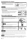
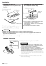
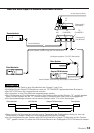
NOTE
1
Switching unit.......................................1
2
Controller (cord length: 5 m) ...............1
3
Connection cable (2 m) ........................1
4
Velcro strip............................................2
5
Self-tapping screw(
φ
4
×
16 mm).........2
6
Cable band ............................................1
7
Double-sided adhesive tape ................1
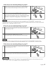
Components
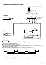
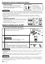
Controller2
TO
CONTROLLER
TO
H/U
TO
CHANGER 1
TO
CHANGER 2
Switching unit1
(Rear side)
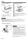
Connection
To the external unit
AV
IN