


6 English
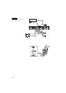
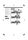
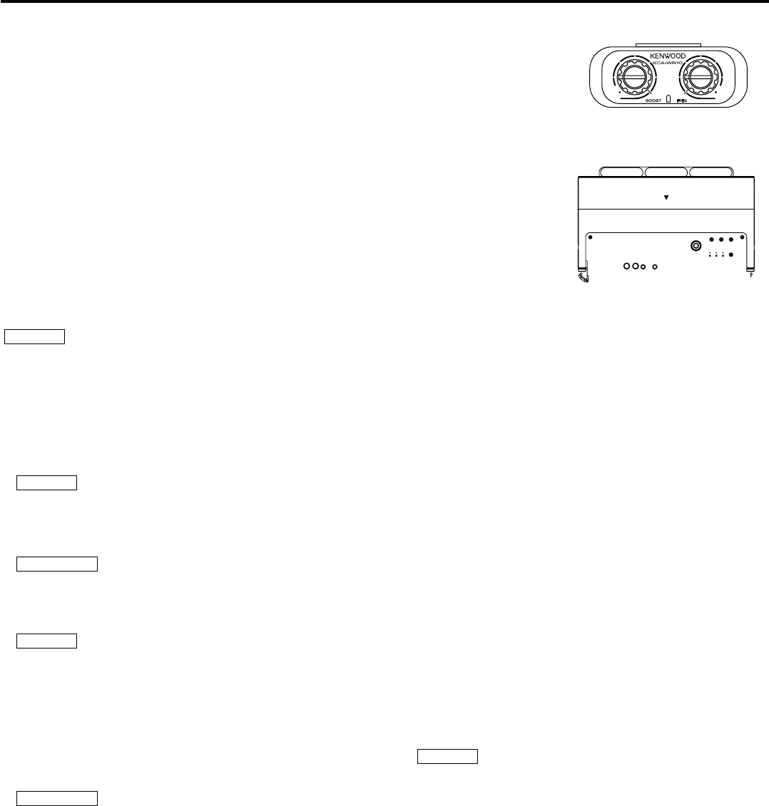
Controls
NOTE
The control panel locates under the dressing cover. Remove the cover to
access to its controls for adjustment. (See page 3)
1 Fuse (25 A × 3)
2 Battery terminal
3 Ground terminal
4 Power control terminal
Controls the unit ON/OFF.
NOTE
Controls the unit power. Be sure to connect it with all the systems.
5 Speaker output terminals
As this unit accepts speakers with a minimum impedance of 1 ohm, connect
speakers with 1-ohm or higher impedance to these terminals.
2CAUTION
The rated input of the speakers should be no less than the maximum output
of the amplifier. Otherwise malfunction may result.
6 REMOTE terminal
Connects the Remote cable.
NOTE
Use the Remote cable of the accessory.
7 LINE OUT FILTER switch
Changing over the audio signal output to the "LINE OUT" terminal.
ON position:
The audio signal adjusted when setting "LPF", "INPUT SENSIVITY" control and
Bass boost is output to the "LINE OUT" terminal.
OFF position:
The audio signal input from the "LINE IN" terminal is output to the "LINE OUT"
terminal (through output).
2CAUTION
The volume of the audio output to the "LINE OUT" terminal is different in
"ON" and "OFF" position. Remember this when changing the "LINE OUT
FILTER" switch from "ON" to "OFF".
8 RESET button
Resets the microprocessor of the unit.
9 LINE IN terminal
0 LINE OUT terminal
The audio signal set with the "LINE OUT FILTER" switch will be output.
! Power indicator
Lights when the POWER switch is turned On.
The indicator flashes several seconds when the POWER switch is turned On
or when the Protection function is activated.
@ Control knob
Allows you to switch between and determine Menu System items.
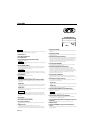
# PHASE switch
When this switch is set "180°" (Reverse) the speaker output phase is reversed.
$ ISF (infrasonic filter) switch
When this switch is set to "ON", the inaudible, ultralow frequencies below the
frequency set with the "ISF FREQUENCY" control are cut off. This improves
the reproduction performance of the speakers by eliminating unnecessary
oscillations which will not become sound.
% ISF FREQUENCY control
Sets the cutoff frequency when the "ISF" switch is set to "ON".
^ BRF (band reject filter) switch
When this switch is set to "-6dB"/"-12dB", frequencies in the band set with the
"B.R.F. FREQUENCY" control are rejected and eliminated. The band rejection
allows to reduce resonance inside the vehicle compartment and standing
waves. (page 7)
& B.R.F. FREQUENCY control
Sets the rejection frequency when the "BRF" switch is set to "-6dB"/"-12dB".
(page 7)
* LPF(Low-Pass Filter) switch
This switch allows to apply low-pass filtering to the speaker outputs.
• OFF position:
The entire bandwidth is output without filtering.
• ON position:
The filter outputs the band of lower frequencies than the frequency set
with the "LPF FREQUENCY" control.
( INPUT SENSITIVITY control
Set this control according to the pre-output level of the center unit
connected with this unit.
NOTE
For the pre-output level, refer to the <Specifications> in the instruction
manual of the center unit.
) LPF(Low-Pass Filter) FREQUENCY control
Sets the cutoff frequency when the "LPF" switch is set to "ON".
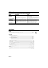
* BOOST LEVEL (Bass boost level) control
Sets the level by which the low frequency range should be boosted.
( Power indicator
) FREQUENCY (Bass boost frequency) control
Sets the center frequency around which the low frequency range should be
boosted.