


6 English
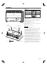
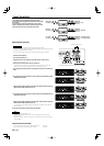
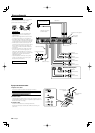
Controls
NOTE
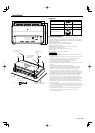
The control panel locates under the dressing cover. Remove the cover to
access to its controls for adjustment. (See page 3)
This is a 4 channel amplifier including 2 stereo amplifiers in a body. One
amplifier is referred to as amplifier A and the other is amplifier B. This unit
is compatible with a large variety of systems by combining the switches and
functions described in the following.
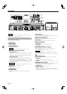
1 Fuse (25 A × 3)
2 Battery terminal
3 Ground terminal
4 Power control terminal
Controls the unit ON/OFF.
NOTE
Controls the unit power. Be sure to connect it with all the systems.
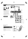
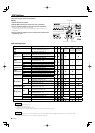
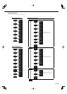
5 Speaker output terminals (A.ch/B.ch)
• Stereo Connections:
When you wish to use the unit as a stereo amplifier, stereo connections are
used.
The speakers to be connected should have an impedance of 2 or greater.
When multiple speakers are to be connected, ensure that the combined
impedance is 2 or greater for each channel.
• Bridged Connections:
When you wish to use the unit as a high-output monaural amplifier,
bridged connections are used. (Make connections to the LEFT channel 9
and the RIGHT channel · SPEAKER OUTPUT terminals.)
The speakers to be connected should have an impedance of 4 or greater.
When multiple speakers are to be connected, ensure that the combined
impedance is 4 or greater.
2CAUTION
The rated input of the speakers should be no less than the maximum output
of the amplifier. Otherwise malfunction may result.
6 RESET button
Resets the microprocessor of the unit.
7 LINE IN terminal
8 LINE OUT terminal
Outputs the audio signal set in DSP settings (stereo or center speaker/
subwoofer).
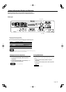
9 Power indicator
Lights when the POWER switch is turned On.
The indicator flashes several seconds when the POWER switch is turned On
or when the Protection function is activated.
0 MODE switch (A/B/LINE OUT)
This switch selects the channel set in DSP settings (A, B, LINE OUT).
! Control knob
Allows you to switch between and determine Menu System items.
@ DISP switch (SET/INFO)
• INFO position:
Sets <Status Information Display and Settings> (page 7).
• SET position:
Sets <DSP Settings> (page 8).
# INPUT SENSITIVITY control (A.ch/B.ch)
Set this control according to the pre-output level of the center unit
connected with this unit.
See <Input Sensitivity> (page 10) for details on setting.
NOTE
• For the LINE OUT level, refer to the <Specifications> in the instruction
manual of the center unit.
• When A is selected with the INPUT SELECTOR switch, the control portion for
cannot be used.
$ INPUT SELECTOR switch
This switch selects the input method of the signals to be amplified by
amplifiers A and B.
• A B position:
Amplifies both of the signals input to amplifiers A and B.
• A position:
Amplifies only the signal input to amplifier A with both amplifiers A and B.
% OPERATION switch (A.ch/B.ch)
The amplification methods of the signals input to amplifiers A and B can be
selected independently according to the setting of this switch.
• STEREO position:
The amplifier can be used as a stereo amplifier.
• MONO (Lch) position:
Amplifies the signal input from the left side only. Set to this position and
make bridged connections to use as a high-power monaural amplifier. (The
input right signal is not output.)
96 78
!0
45321
%
@
#
$