


English 5
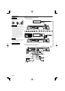
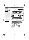
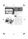
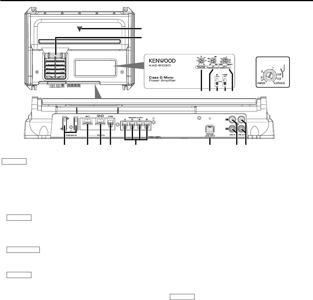
Controls
NOTE
The control panel locates under the dressing cover. Remove the cover to
access to its controls for adjustment. (See page 3)
1 Fuse (30 A × 2)
2 Battery terminal
3 Ground terminal
4 Power control terminal
Controls the unit ON/OFF.
NOTE
Controls the unit power. Be sure to connect it with all the systems.
5 Speaker output terminals
As this unit accepts speakers with a minimum impedance of 1 ohm,
connect speakers with 1-ohm or higher impedance to these terminals.
2CAUTION
The rated input of the speakers should be no less than the maximum output
of the amplifier. Otherwise malfunction may result.
6 Speaker level input terminals
NOTE
• The genuine-accessory car stereo shall have a maximum power output of
no more than 40 W.
• Do not connect the speaker output leads from a power amplifier (Optional)
to the speaker level input terminals of this unit, for this may cause
malfunction or damage.
• Do not connect cables and leads to both RCA cable input jacks and
the speaker level input terminals simultaneously, for this may cause
malfunction or damage.
• Connect the power control lead to a power supply which can be turned
ON/OFF by the ignition key switch (ACC line). With this connection, shock
noise may be generated when the power of the genuine-accessory car
stereo is switched ON/OFF.
7 LINE IN terminal
8 LINE OUT terminal
The signal that’s input from the line input terminal is output.
9 Power indicator
When the power is turned on, the Power indicator lights.
If the Power indicator does not light when the power is turned on, the
protection function may be activated. Check whether there is any indication
of trouble. (See page 2)
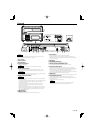
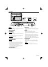
0 Illumination
! BASS BOOST LEVEL control
Sets the low frequency level to be compensated.
@ LPF(Low-Pass Filter) FREQUENCY control
This control adjusts the frequency band output from this unit.
# ISF (infrasonic filter) switch
Ultralow frequencies that cannot be reproduced even by a subwoofer
speaker do not become sound but become unnecessary oscillations, which
affect the sound by causing distortion, etc. Setting this switch to "15 Hz" or
"25 Hz" cuts the frequencies below the respective frequency.
This improves the reproduction performance of the speakers by eliminating
unnecessary oscillations which will not become sound.
$ PHASE switch
When this switch is set "180°" (Reverse) the speaker output phase is reversed.
% INPUT SENSITIVITY control
Set this control according to the pre-output level of the center unit
connected with this unit, or to the maximum power output of the genuine-
accessory car stereo.
Use the diagram on the right as a guide.
NOTE
For the pre-output level or the maximum power output, refer to the
<Specifications> in the instruction manual of the center unit.
30
30
q r s t u v w
x
y
z{| ~
~
}
15W – 40W
p