


6
Connecting to a Receiver or Amplifier
Chapter 1Chapter 2Chapter 3Chapter 4Chapter 5Chapter 6Chapter 7
R
L
OUTPUT
SYSTEM
CONTROL
DIGITAL
OUT
A
B
SL16
TEXT
OPTICAL
TEXT
DIGITAL
OUT
OPTICAL
TEXT
SYSTEM
CONTROL
OPTICAL
TEXT
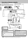
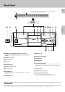
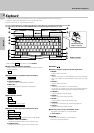
Connecting to a Receiver or Amplifier
To wall AC
outlet
Audio
cable
Receiver or Amplifier, etc.
Digital component (MD,DAT, etc.)
DIGITAL INPUT (OPTICAL)
Optical digital cable
(Commercially-available)
Optical digital cable
(Commercially-available)
Communica-
tion cable
System
control
cable
Audio
cable
CD1
CD2
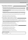
DIGITAL OUT jack (OPTICAL)
Remove the cap
Remove the protective cap before using the DIGITAL
OUT jack.
DTS Disclaimer clause
When playing DTS-encoded CDs, excessive noise will be ex-
hibited from the analog stereo outputs. To avoid possible
damage to the audio system, the consumer should take proper
precautions when the analog stereo outputs of the CD player
is connected to an amplification system. To enjoy DTS Digital
Surround™ playback, an external 5.1 channel DTS Digital Sur-
round™ decoder system must be connected to the digital out-
put (S/P DIF, AES/EBU, or TosLink) of the CD player.
* 2
Note on the SL-16 TEXT jack
When using a KENWOOD Receiver equipped with the SL-16 TEXT
jack, connect it to the Receiver using the communication cable
provided with this unit. This makes it possible to display the
disc and track titles on the LCD remote control unit (provided
with the Receiver).
If your receiver has the SL16/XS8 mode select switch,
set the connected receiver to the [SL16] mode.
Note
Note
NotesNotes
Notes
1. Connect all cables firmly. If connections are loose, there could be loss of sound or noise produced.
2. When plugging and unplugging connection cables, be sure to first remove the power cable from the AC outlet. Plugging/unplugging
connection cables without removal of the power cable can cause malfunctions or damage to the unit.
Make connections as shown below.
When connecting the related system components, refer
also to the instruction manuals of the related components.
Do not plug in the power lead until all connections are com-
pleted.
* 1
OUTPUT A:
Analog output from Player A.
OUTPUT B:
Analog output from Player B.
*1
*2