


1
2
3
4
5
6
7
8
9
10
11
12
13
14
15
16
17
18
19
20
21
22
23
96
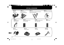
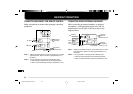
EQUIPMENT CONNECTIONS
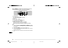
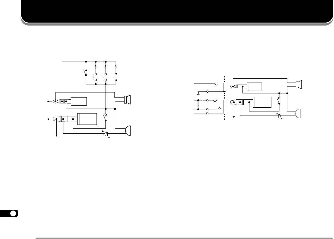
CONNECTING EQUIPMENT FOR REMOTE CONTROL
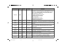
Make connections as shown when remotely controlling
equipment.
Note 1: Voltage is developed across the 100
Ω
resistor in the 3.5 V line
in the transceiver. When 2 mA flows, approximately 3.3 V is
developed.
Note 2: A 10
µ
F capacitor is not required in the following cases:
•
When the other equipment has DC blocking capacitors.
•
When a 2-terminal electret condenser microphone is used.
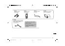
External
microphone
Ø3.5
plug
Ø2.5
plug
External
speaker
SW-2 10K
SW-3 27K
SW-1 3.9K
Lock SW
MIC jack
Note 1
SP jack
PTT switch
Note 2 10 µF
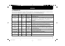
CONNECTING OTHER EXTERNAL EQUIPMENT
When connecting an external speaker, an external
microphone, or other equipment such as a TNC for
packet radio to the SP jack or MIC jack, refer to the
diagram below.
Note 1: Voltage is developed across the 100
Ω
resistor in the 3.5 V line
in the transceiver. When 2 mA flows, approximately 3.3 V is
developed.
Note 2: A 10
µ
F capacitor is not required in the following cases:
•
When the other equipment has DC blocking capacitors.
•
When a 2-terminal electret condenser microphone is used.
Speaker
Ground
MIC
Note 2 10µF
PTT switch
PTT
External
speaker,
Note 1
External
microphone,
TNC RX, etc.
TNC TX, etc.
SP
MIC
PTT
Ø2.5
plug
Ø3.5
plug
3.5 V
3.5 V100 Ω
TH-D7 E 96 Equipment Connec. 98.12.4, 0:14 PM96