5. ENGLISH INSTRUCTIONS
5
Model PSW2500 Rear Panel
1. Line in input sockets
2. High pass output sockets
3. Ground in / out
4. Level control
5. Music / cinema
6. Crossover Frequency control
7. Slope
8. Phase control
9. Mains indicator light Power ON
Power OFF
10. Auto/manual switch
11. ‘ON/OFF’ switch (vacation switch)
12. AC power input (230V Euro SP 3333 AA)
(230V UK SP 3333 AC)
(115V US SP 3333 AB)
FAULT
Mains indicator light does not come on.
If the mains indicator light still does not come on.
If the mains indicator light is on but no sound
comes from the subwoofer.
If there is still no sound.
REMEDY
Check that the subwoofer is plugged into the mains supply and that any switches are on.
Check any fuses (including the plug) or circuit breakers on the mains supply which may effect
the power to the subwoofer.
Contact your dealer for further advice.
Ensure that all equipment is switched on.
Check and adjust the level control.
Check that the output sockets on the source equipment are correctly switched and
adjusted to provide sufficient level to drive the subwoofer.
Check that all connections between the subwoofer and the source equipment are
correct and adjust as necessary.
Contact your dealer for further advice.
As the sub-bass (low frequency) sound produced by the
subwoofer is non-directional it can be positioned almost
anywhere in the room, although it should not be placed too close to the
listener. If possible try the subwoofer in different positions to find the best
place for a boom-free sound.
Front speakers full range - speakers capable of producing full
frequency range.
A. Line Level - connected to amplifier processor loop.
B. Line level inputs - connected to subwoofer output on amplifier by
single (C1) or ‘Y’ (C2) cable.
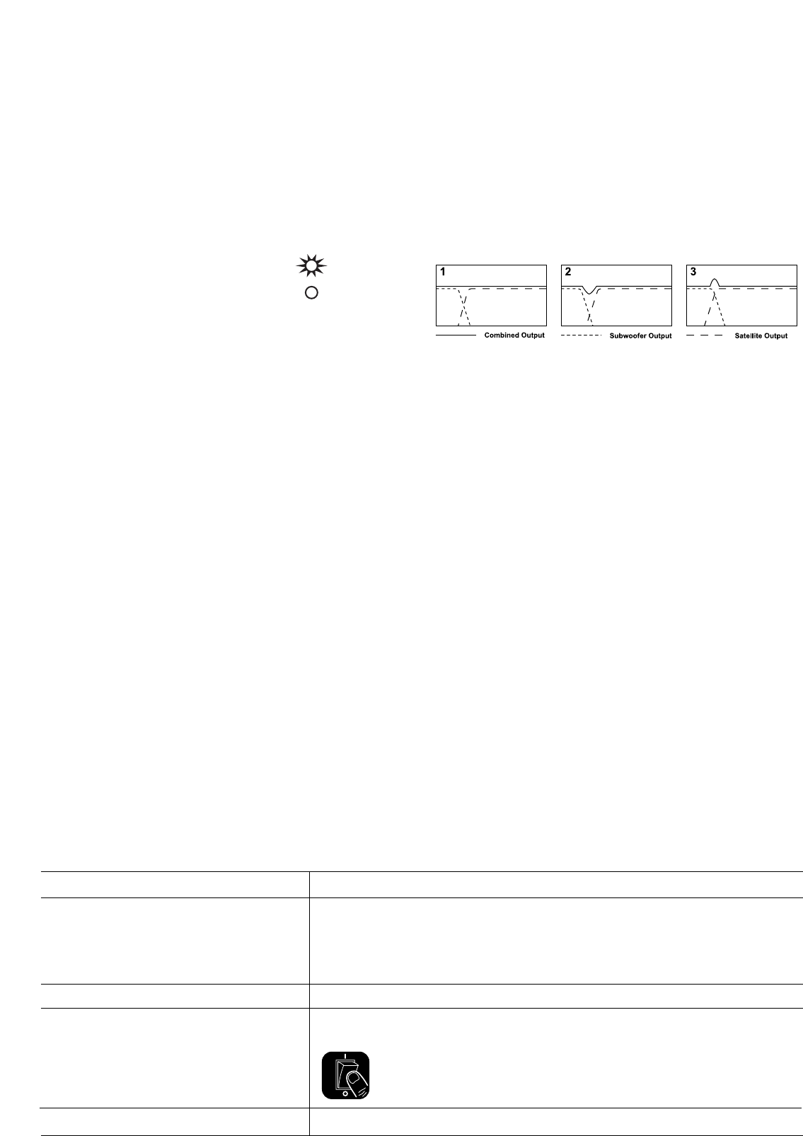
A. Crossover Frequency Control
The frequency control changes the upper cut-off frequency of the
subwoofer. Its effective range is from 15Hz to 140Hz at a rate of
12dB/24dB per octave. The frequency control should be adjusted to
achieve the smoothest integration between the main/satellite speakers
and the subwoofer.
Clockwise rotation will increase the cut-off frequency and
anti-clockwise rotation will decrease the cut-off frequency.
1. Ideal Crossover - Flat Response.
2. Crossover point set too low - Causes Dip in combined response.
3. Crossover Point set too high - Causes hump in combined response.
B. Phase Control
The phase control will normally be set at 0° but more output level can
sometimes be achieved in the 180° position, particularly when the
subwoofer is far away from the satellite speakers.
C.Volume Control
The volume control adjusts the output level of the subwoofer in relation to
the satellite or AV speaker output level. Clockwise rotation to increase the
output level or anti-clockwise to decrease the output level.
D. Auto/Manual Switch
It enables / disables the input to your subwoofer to be muted. Setting this
switch to Auto position, the subwoofer will mute the input automatically if
it is idled for about 45 minutes. It resumes to work instnataneously after a
signal is applied. If Manual is set, the unit will never be muted even when
idle.
E. Ground In/Out
Enhances compatibility. Used to break possible earth loops which cause
audible hum.
F. Music/Cinema
This switch selects one of two characteristics: Music is selected to give
deep, clean bass; Cinema is selected to give cinematic impact.
G. Slope
Used to adjust transition between speakers and subwoofer.
6 Controls and sockets
7 Positioning
8 Connections
8 Adjusting the controls
Fault Finding


