


7
English
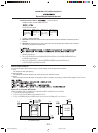
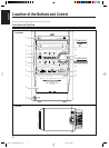
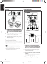
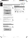
INPUT INPUT INPUT INPUT
RIGHT
LEFT
MAIN SPEAKERS
CAUTION: SPEAKER IMPEDANCE 6 -16
SUBWOOFERS
RIGHT
LEFT
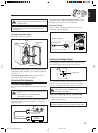
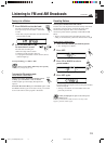
1 If the cords are covered with insulation,
remove a short section of insulation at the
end of each cord by twisting and pulling it
off.
2 Connect the AM loop antenna to the AM
LOOP terminals as illustrated.
3 Turn the AM loop antenna until you have
the best reception.
To connect an outdoor AM antenna
When reception is poor, connect a single vinyl-covered wire
to the AM EXT terminal and extend it horizontally. The AM
loop antenna must remain connected.
For better reception of both FM and AM
• Make sure the antenna conductors do not touch any other
terminals and connecting cords.
• Keep the antennas away from metallic parts of the unit,
connecting cords, and the AC power cord.
AM antenna
Vinyl-covered wire
(not supplied)
AM loop antenna
(supplied)
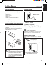
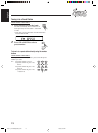
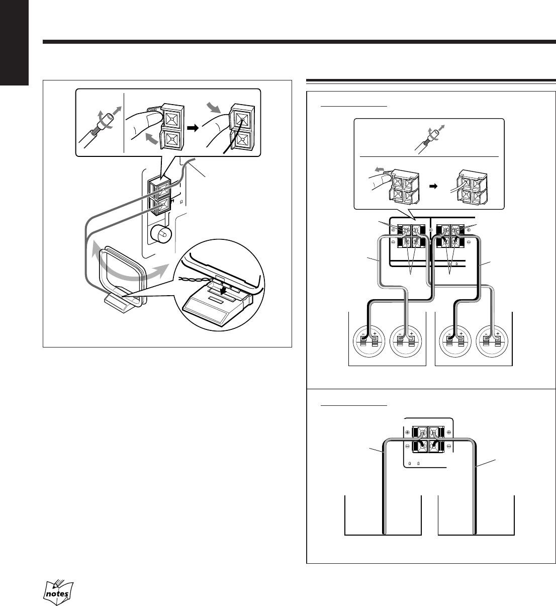
Connecting Speakers
Speaker cord
Speaker cord
FM 75
COAXIAL
AM EXT
AM LOOP
ANTENNA
12
3
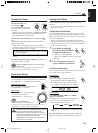
RIGHT
SPEAKER
IMPEDANCE
6 - 16
LEFT
SPEAKERS
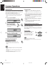
FOR UX-J66V:
Right speaker Left speaker
FOR UX-J55V:
Right speaker Left speaker
Speaker
cord
Speaker
cord
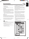
1
2
3
Black
Red
Blue
Gray
1 If the cords are covered with insulation,
remove a short section of insulation at the
end of each cord by twisting and pulling it
off.
2 Press and hold the clamp of the speaker
terminal as illustrated.
3 Insert the end of the speaker cord into the
terminal.
Match the polarity between the unit and the speaker
terminals: ª to ª and · to ·.
4 Release your finger from the clamp.
EN01-14_UX-J66&55[US/UN]1.pm6 20/6/03, 3:04 PM7