


5
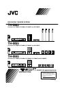
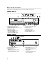
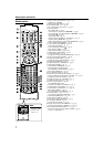
Names of parts and controls
The illustrations of the center unit and the subwoofer used in this manual are of TH-M65 unless otherwise noted.
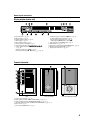
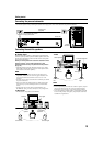
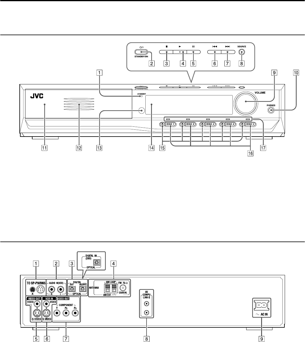
Front panel (center unit)
A
Standby lamp (STANDBY)
A
pg. 19
B
Standby-on button (
F
STANDBY/ON)
A
pg. 19
C
Stop button (
7
)
A
pg. 23
D
Play button (
3
)
A
pg. 23
E
Pause button (
8
)
A
pg. 23
F
Reverse skip button (
4
)
A
pg. 26
G
Forward skip button (
¢
)
A
pg. 26
H
Source button (SOURCE)
A
pg. 20
I
Volume control (VOLUME)
A
pg. 20
J
Headphones jack (PHONES)
A
pg. 20
K
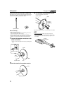
Disc trays
A
pg. 23
L
Illumination lamp
A
pg. 20
M
Remote sensor
A
pg. 16
N
Display window
A
pg.6,24
O
Open/close buttons (
0
)
A
pg. 23
P
Disc buttons (DISC 1-5)
A
pg. 23
Q
Disc lamps (TH-M65 only)
A
pg. 25
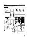
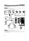
Rear panel (center unit)
A
System cord connector
A
pg. 10
B
Audio input jacks (AUDIO IN (VCR))
A
pg. 14
C
Digital input/output jacks
(DIGITAL IN/OUT) (TH-M65)
A
pg. 14
Digital input jack
(DIGITAL IN) (TH-M55/TH-M45)
A
pg. 14
D
Antenna terminals (ANTENNA)
A
pg. 9
E
Video output jacks (VIDEO OUT)
A
pg. 8
VIDEO, S-VIDEO
F
Video input jacks (VCR IN)
A
pg. 14
VIDEO, S-VIDEO
G
Video output jacks (VIDEO OUT)
A
pg. 8
COMPONENT (Y, P
B
,P
R
)
H
AV COMPU LINK-III jacks
A
pg. 55
I
Ó
AC IN socket
A
pg. 15
For TH-M55/TH-M45