


4
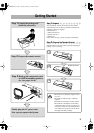
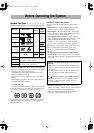
Step
3
: Hook Up
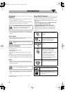
If you need more detailed information, see page 6.
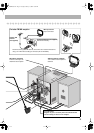
TV
AUX
DECODER
LEFT
RIGHT
AUDIO OUT
OPTICAL
DIGITAL IN
VIDEO INPUT
VIDEO INPUT
Y
P
B
P
R
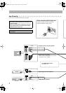
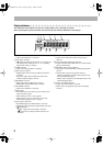
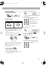
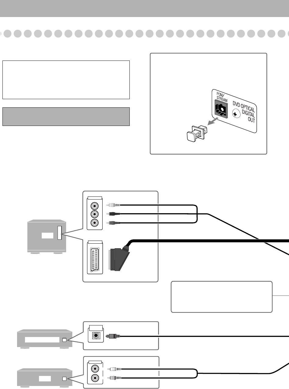
Illustrations of the input/output terminals below are
typical examples.
When you connect other components, refer also to
their manuals since the terminal names actually
printed on the rear may vary.
Turn the power off to all components before
connections.
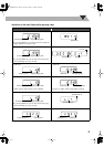
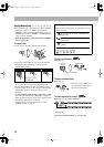
Audio cord (not supplied)
White
Red
Optical digital cord (not supplied)
Component video cord (not supplied)
Red
Blue
Green
SCART cord (not supplied)
• This connection only sends the video signals
(Composite, Y/C, or RGB).
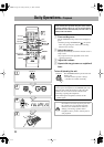
AV COMPU LINK terminal
• For future use.
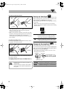
Before connecting optical digital cord
Remove the protective cap from the DVD
OPTICAL DIGITAL OUT terminal.
OR
VCR, etc.
Connection.fm Page 4 Tuesday, February 17, 2004 10:25 PM