


4
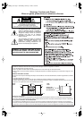
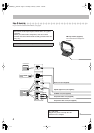
Step
3
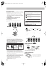
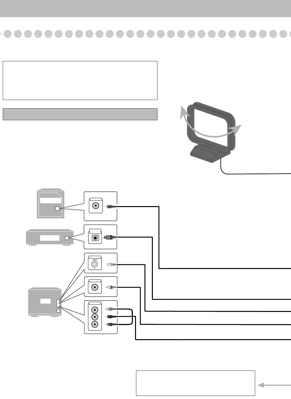
: Hook Up
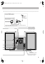
If you need more detailed information, see page 6.
SUBWOOFER
TV
DECODER
OPTICAL
DIGITAL IN
VIDEO INPUT
VIDEO INPUT
AUDIO INPUT
Pb
Pr
Y
VIDEO INPUT
Illustrations of the input/output terminals below are typical
examples.
When you connect other components, refer also to their
manuals since the terminal names actually printed on the rear
may vary.
Turn the power off to all components before connections.
Audio cord (not supplied)
Optical digital cord (not supplied)
Component video cord (not supplied)
Red
Blue
Green
Composite video cord (supplied)
AM loop antenna (supplied)
Turn it until the best reception is
obtained.
To a wall outlet
Plug the AC power cord only after all
connections are complete.
S-VIDEO cord (not supplied)
Yellow
FS-GD7[J]_EN.book Page 4 Thursday, February3, 2005 7:49 PM