


7
Å
ıΉÏÌ
Ç
DVR
OUT(REC)
DVR/DVD
IN(PLAY)
Y
P
B
P
R
COMPONENT VIDEO
MONITOR
OUT
DVR/DVD
IN
VCR(DBS)
IN
DVR
OUT(REC)
DVR/DVD
IN(PLAY)
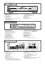
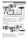
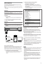
This receiver is equipped with the following video terminals—
composite video, S-video, and component video terminals.
• If your video components have S-video (Y/C-separation) and/or
component video (Y, PB, PR) jacks, connect them using an S-
video cable (not supplied) or component video cable (not
supplied). By using these terminals, you can get better picture
quality in the order:
Component > S-video > Composite
IMPORTANT:
This receiver can convert video signals as follows:
• Composite video signals can be converted into both S-video
signals and component signals.
• S-video signals can be converted into component signals.
• Component signals cannot be converted.
When converting video signals, there are some points to observe.
For details, see “About video signal conversion” on page 10.
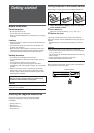
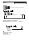
Connecting audio/video components
Do not connect the AC power plug to the wall outlet until all connections are completed.
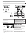
NOTES
• When connecting a DVD recorder or DVD player to the component video input jacks,
select the component video input mode (DVD VIDEO IN) correctly. If you do not, you
cannot view the playback picture on the TV or the AV COMPU LINK remote control
system cannot operate properly. See page 25 for details.
• When using a stereo audio cable as the illustration above, set the audio input mode to
“ANALOG.” For details, see “Selecting the analog or digital input mode” on page 12.
• You can enjoy digital sound if using a digital coaxial or optical cable. When shipped
from the factory, the digital input terminal setting for a DVD recorder and DVD player
is set to use the digital coaxial terminal (DIGITAL IN 1 (DVR/DVD)). For details of
digital connection, see page 10.
Turn off all components before making connections.
• When you connect other components, refer also to their
manuals.
DO NOT use a TV through a VCR or a TV with a built-in
VCR; otherwise, the picture may be distorted.
CAUTION:
If you connect a sound-enhancing device such as a graphic
equalizer between the source components and this receiver, the
sound output through this receiver may be distorted.
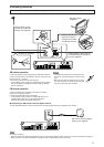
If your video components have AV COMPU LINK terminal
See also page 35 for detailed information about the connection
and the AV COMPU LINK remote control system.
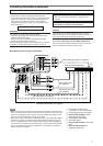
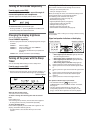
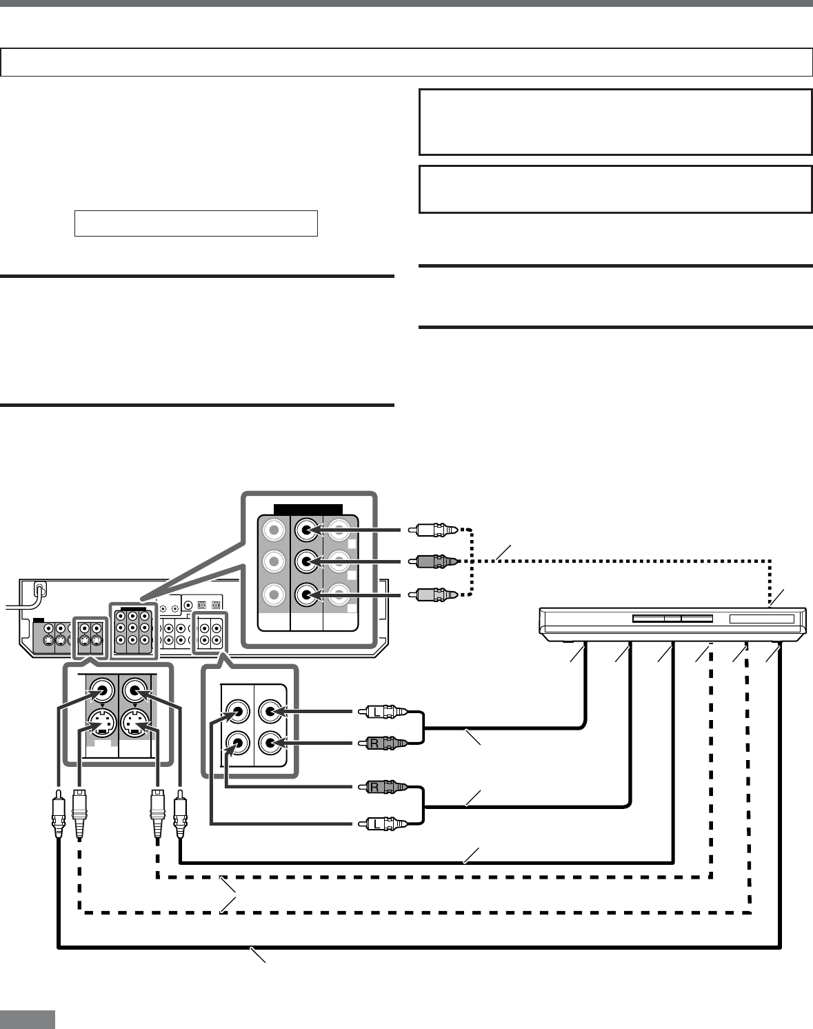
Å To component video output
• Connect Y, P
B, and PR correctly.
ı To left/right audio channel output
Ç Only for DVD recorder: To left/
right audio channel input
Î To composite video output
‰ To S-video output
Ï Only for DVD recorder: To S-video
input
Ì Only for DVD recorder: To
composite video input
7 Connecting a DVD recorder or DVD player
White
Red
DVD recorder or DVD player
White
Red
Stereo audio cable
(not supplied)
Green
Blue
Red
Component video cable (not supplied)
S-video cable (not supplied)
Composite video cable
(not supplied)
Composite video cable (not supplied)