


1
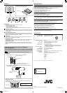
KS-AR8001D
POWER AMPLIFIER: INSTRUCTIONS
AMPLIFICATEUR DE PUISSANCE: MANUEL D’INSTRUCTIONS
ENGLISH
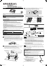
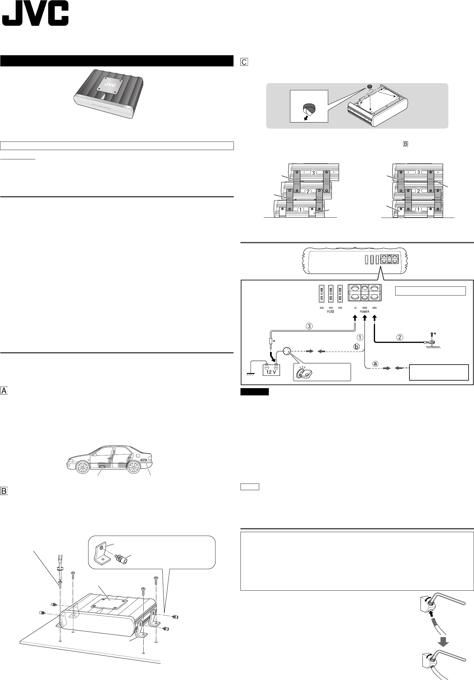
INSTALLATION
The following illustration shows a typical installation. However, you should make adjustments
corresponding to your specifi c car. If you have any questions or require information regarding
installation kits, consult your “JVC IN-CAR ENTERTAINMENT” car audio dealer or a company
supplying the kits.
CAUTION
To prevent short circuits while making connections, keep the battery’s negative terminal
disconnected.
1 Remote turn-on line (not included with this unit)
a When you use a JVC car receiver with a remote lead, connect to the remote lead.
b When you connect a unit without a remote lead, connect to the accessory circuit of the
car which is activated by the ignition switch. In this case, noise may occur when the car
receiver is turned on or off. To avoid this noise, do not turn on or off the car receiver itself.
You can turn on or off the car receiver along with the on/off operation of the ignition switch.
2 Ground lead (not included with this unit)
3 Power cord (not included with this unit)
• When using a power cord, be sure to add a 40 A fuse near the battery as shown.
• Connect to the battery’s “ª” terminal only after all the other connections have been made.
If the Status lamp (see “CONTROLS” on page 3) lights in red, it indicates incorrect speaker
wiring or connections. In this case, see “TROUBLESHOOTING” on page 3. Be sure to correct the
speaker wiring and other connections.
POWER SUPPLY
LVT1812-001A
[E/U]
Thank you for purchasing a JVC product. Please read all instructions carefully before operation,
to ensure your complete understanding and to obtain the best possible performance from the
unit.
For safety....
•
Do not raise the volume level too much, as this will block outside sounds, making driving dangerous.
• Stop the car before performing any complicated operations.
CAUTIONS AND NOTES
This unit is designed to operate on 12 V DC, NEGATIVE ground electrical systems.
• This unit uses BTL (Balanced Transformerless) amplifi er circuitry, i.e., fl oating ground system,
so comply with the following:
Do not connect the “·” terminals of the speakers to each other.
Do not connect the “·” terminals of the speakers to the metal body or chassis.
• Cover the unused terminals with insulating tape to prevent them from short circuiting.
• When an extension lead is used, it should be as thick and short as possible; connect it fi rmly
with insulating tape.
• Be sure to leave an appropriate space between the antenna (aerial) and the wires of this unit.
• When replacing the fuse, only use a 25 A fuse.
• Do not let pebbles, sand or metallic objects get inside the unit.
• To keep the heat dissipation mechanism running effectively, wipe the accumulated dust off
periodically.
• Listening to the tape, radio, CD or Digital Audio Player, etc. with the volume set at a high level
for a long period of time will exhaust the battery, while the engine is turned off or while the
engine is idling.
• This unit becomes very hot. Be careful not to touch the unit not only when using but for a while
after using.
DO NOT disassemble the units since there are no user serviceable parts inside.
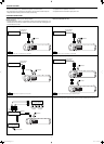
Bracket (I)
Spacer
Spacer
Bottom
When mounting this unit, be sure to use the provided screws. If any other screws are used,
there is a risk of loosening the unit or damaging parts inside it.
• Before drilling holes in the trunk to install the unit, make sure that there is a suffi cient
space under the trunk so that you do not drill holes in the fuel tank, etc.
• To detach and rotate the Logo Plate, use the provided hex wrench (3 mm).
When you use more than one KS-AR8000 series amplifi er, you can pile up to three of
them using the provided brackets and hex screws in two ways, X or Y.
1 Attach the provided spacers to the bottom of the amplifi er (2 and 3).
2 Fix the amplifi ers on both sides with the brackets (I) as illustrated.
• Be sure to mount the lowest amplifi er (1) as illustrated on
.
• Before piling amplifi ers as X, fi rst make the connections for the power supply (see
“POWER SUPPLY” below) and speakers (see “SPEAKER CONNECTIONS” on page 2).
X
Mount this unit on a fi rm surface, such as in the trunk or under the front seat.
• Since heat is generated in the unit, do not mount it near infl ammable objects. In addition,
mount it in an area that will not prevent the unit from dissipating the heat.
• Do not mount the unit in the places subject to heat: near a radiator, in a glove compartment
or in insulated areas such as under a car mat that will prevent the unit from dissipating
heat.
• When mounting the unit under the front seat, make sure that adjusting the seat position
will not catch any wire of the unit.
Under the front seat Onto the trunk fl oor
Bracket (I)
Bracket (L)
Bracket (L)
*Not included with this unit.
To metallic body or chassis
(To an accessory terminal)
Fuse
Car battery
Ignition switch
Spacer's bottom
Logo Plate (detachable)
Drilled hole
Bracket (L)
Hex Screw (M4 × 10 mm)
Bracket (L)
Y
This unit is designed to be connected to subwoofers.
Note
Side of the unit
JVC car receiver, etc.
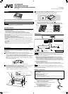
TERMINAL CONNECTIONS
1 Peel off the insulating vinyl cover of a lead to expose the conductor
inside.
• The exposed conductor should be 7 mm to 10 mm long.
– If shorter, it may cause poor conductivity.
– If longer, it may cause a short circuit.
2 Loosen the hex screw in a terminal with the provided hex wrench
and insert the conductor into the terminal.
• Use the appropriate hex wrench for each terminal.
– 4 mm: +B and GND terminals
– 3 mm: REM and SPEAKER OUTPUT terminals
3 Fix the hex screw again to secure the conductor.
Remote turn-on line
1207KMMMDWTKC
EN, FR
© 2007 Victor Company of Japan, Limited
Screw (φ 4 × 20 mm)
The appropriate wire gauge for each terminal is as follows.
• POWER terminals:
– + B and GND: Cross section of 8 mm
2
to 21 mm
2
– REM: Cross section of 0.8 mm
2
to 8 mm
2
• SPEAKER OUTPUT terminals:
– Cross section of 0.8 mm
2
to 8 mm
2
If you have any questions regarding the thickness of the power cord, etc., consult your nearest
“JVC IN-CAR ENTERTAINMENT” car audio dealer.
EN_KS-AR8001D[EU]2.indd 1EN_KS-AR8001D[EU]2.indd 1 07.12.10 8:12:00 PM07.12.10 8:12:00 PM